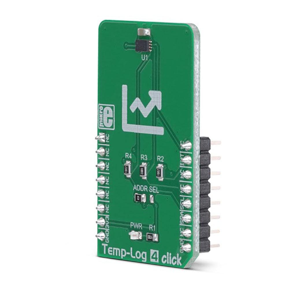
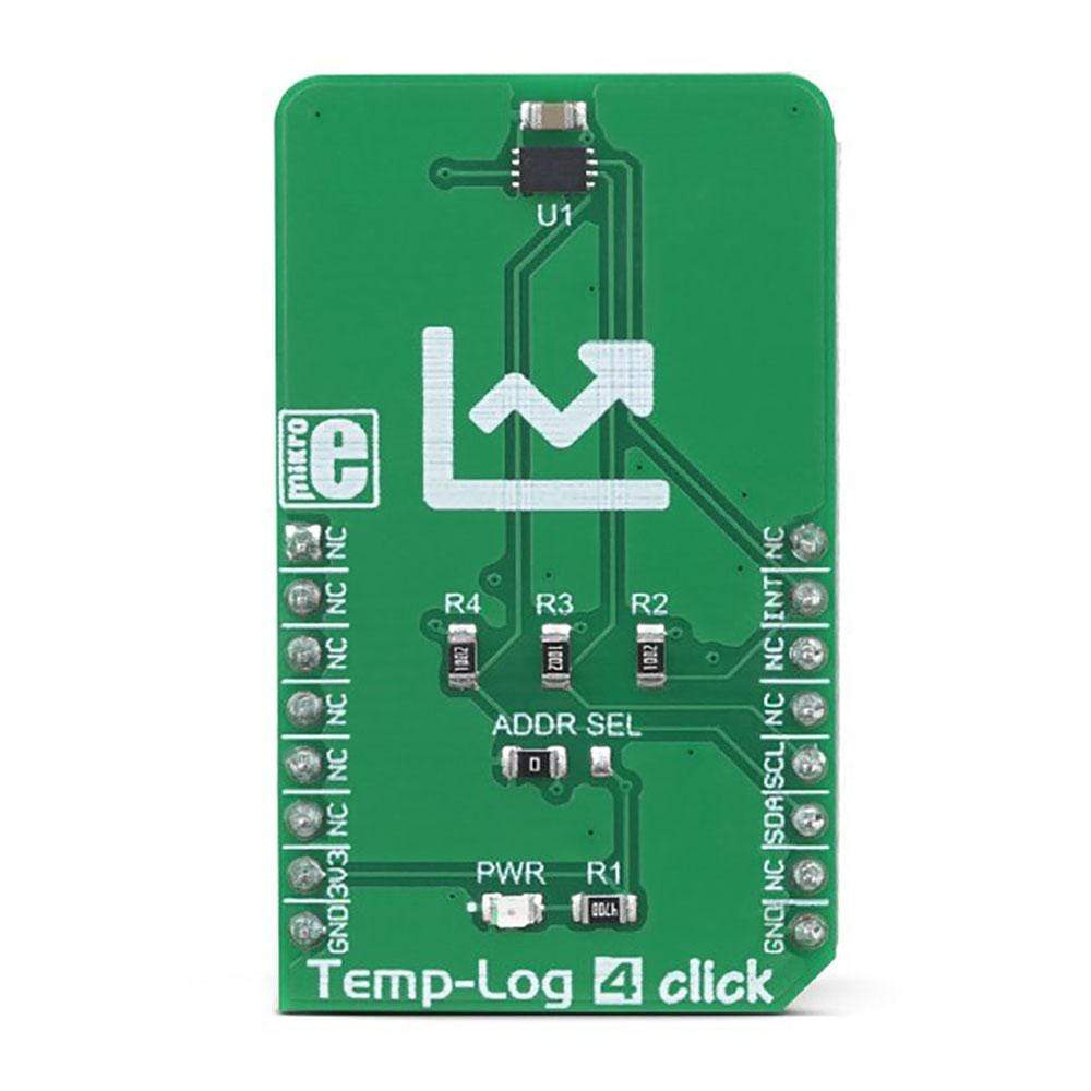
Temp-Log 4 Click Board
Overview
The Temp-Log 4 Click Board™ measures temperature and features the SE97B IC, an accurate temperature sensor IC with integrated EEPROM. Besides the thermal sensor, this IC is equipped with additional 256 bytes of EEPROM, integrated on the same die. This can be a very useful option for some applications: it allows auxiliary data to be stored within the same IC, so no additional EEPROM IC is required. This can simplify the design greatly, reducing the number of required external components.
The SE97B IC meets JEDEC specification JC42.4-TSE2002B1, making it a viable solution for a memory module thermal sensor component. The SE97B is designed specifically for DRAM DIMMs (Dual In-line Memory Modules), allowing the Serial Presence Detect (SPD) feature. However, its use is not limited only to provide the SPD feature. The presence of EEPROM can be utilized for many different tasks: recording of temperature peaks, storage of event alerts, and similar. This makes the Temp-Log 4 Click Board™ a great solution for the development of various embedded applications based on temperature measurement and data logging.
How Does The Temp-Log 4 Click Board™ Work?
The Temp-Log 4 Click Board™ is equipped with the SE97B IC, a temperature sensor with integrated EEPROM, by NXP. This IC is used to convert the temperature measurement into digital information. Besides the thermal sensor, this IC also features 256 bytes of EEPROM on the same die. It is compliant with the JEDEC specification JC42.4-TSE2002B1 since it is designed specifically for DRAM DIMMs (Dual In-line Memory Modules), allowing the Serial Presence Detect (SPD) feature. However, it is not limited to this role only: it can be used as a very accurate general-purpose thermometer with the added benefit of integrated EEPROM, reducing the number of physical ICs required to design a temperature logging application. Temp-Log 4 click utilizes the I2C serial interface (SMBus compatible), which allows it to be used in a wide range of applications.
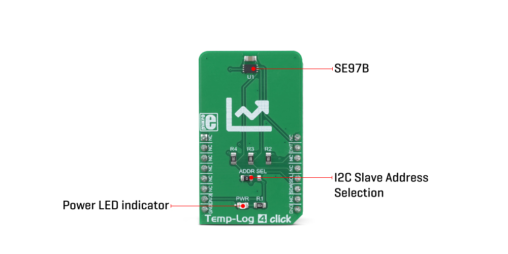
The temperature sensor section includes all the features typically found on such ICs. The band gap thermal sensor is sampled by a 11-bit delta-sigma A/D converter. It is sampled about 10 times per second, and the thermal value is placed on the double-buffered output register. This prevents data corruption if access to the output registry is attempted during the conversion process. The specified accuracy of the temperature sensor is typically ±2 °C in the range from -40 °C to +125 °C, further improving near the operating temperature of DIMM, within the range between +40 °C to +125 °C.
The SE97B IC features the CAPABILITY register. This register is a read-only register and it provides some general information, such as the factory-specified accuracy in the upper-temperature range (+75°C to +95°C and +40°C to +125°C), measurement range, resolution, and other parameters of the sensor. Its description, along with the description of other registers, can be found in the SE97B IC datasheet.
The SE97B IC is fully configurable. It contains a set of registers for configuring the thermal sensor, the upper and the lower thermal limit, as well as the critical temperature. This IC features a very usable interrupt engine, designed mainly to support SPD functionality, but it can be utilized for much wider range of applications. The #EVENT pin is an open-drain, active-LOW pin used to alert the host microcontroller (MCU) or some other circuit, whether the programmed thresholds have been exceeded, or a critical temperature level has been reached. The SE97B allows two EVENT modes: the interrupt mode, and the comparator mode. The interrupt mode can be used in the embedded applications controlled by a MCU, while the comparator mode is used to directly control a circuit, since unlike the interrupt mode, it does not require the software to clear the Both the temperature and the EEPROM section have their own I2C address. The I2C address is determined by four fixed bit values, while the last three bits (LSBs) are determined by the logic states applied to A2, A1, and A0. While A0 and A1 address are hard-wired to a LOW logic level on this Click board™, the value of the A2 address bit can be changed by switching the SMD jumper labelled as ADDR SEL to either 0 (tied to GND) or 1 (tied to VCC). The datasheet of the SE97B offers a table with the content of these four bits for each section of the IC.
The Temp-Log 4 Click Board™ uses the I2C communication interface. It has pull-up resistors connected to the mikroBUS™ 3.3V rail. A proper conversion of logic voltage levels should be applied before the Click board™ is used with MCUs operated with 5V.
SPECIFICATIONS
Type | Temperature & humidity,Temperature Logging |
Applications | The Temp-Log 4 Click Board™ is a great solution for the development of various embedded applications based on temperature measurement and data logging. |
On-board modules | SE97B IC, a temperature sensor with integrated EEPROM, by NXP. |
Key Features | A very high measurement accuracy and repeatability, programmable thresholds and hysteresis, a dedicated EVENT pin with a programmable function, selectable resolution, 256 bytes of integrated EEPROM, and more. |
Interface | I2C |
Compatibility | mikroBUS |
Click board size | M (42.9 x 25.4 mm) |
Input Voltage | 3.3V |
PINOUT DIAGRAM
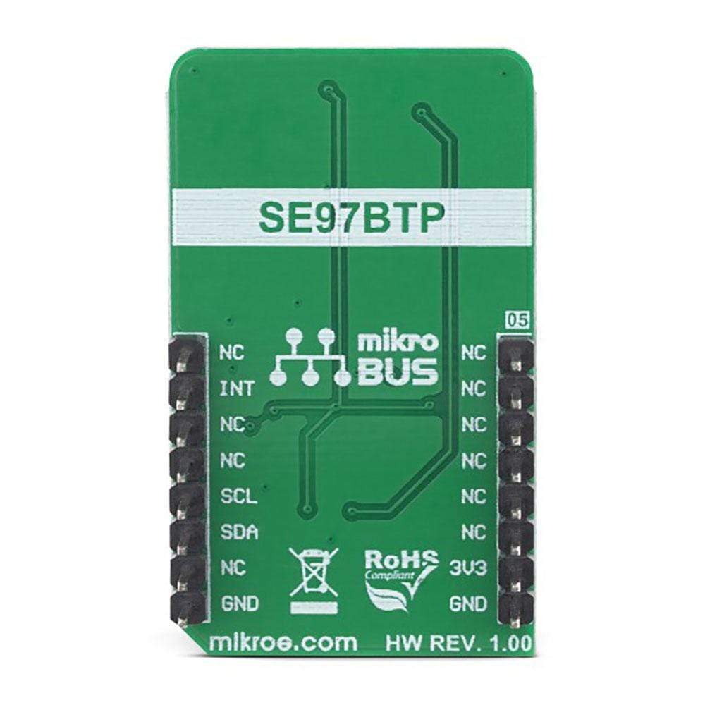
This table shows how the pinout of the Temp-Log 4 Click Board™ corresponds to the pinout on the mikroBUS™ socket (the latter shown in the two middle columns).
Notes | Pin | Pin | Notes | ||||
---|---|---|---|---|---|---|---|
NC | 1 | AN | PWM | 16 | NC | ||
NC | 2 | RST | INT | 15 | INT | Alert OUT | |
NC | 3 | CS | RX | 14 | NC | ||
NC | 4 | SCK | TX | 13 | NC | ||
NC | 5 | MISO | SCL | 12 | SCL | I2C Clock | |
NC | 6 | MOSI | SDA | 11 | SDA | I2C Data | |
Power Supply | +3V3 | 7 | 3.3V | 5V | 10 | NC | |
Ground | GND | 8 | GND | GND | 9 | GND | Ground |
ONBOARD SETTINGS AND INDICATORS
Label | Name | Default | Description |
---|---|---|---|
PWR | PWR | - | Power LED indicator |
ADDR SEL | ADDR SEL | Left | I2C slave address selection: left position 0 (GND), right position 1 (VCC) |
Software Support
We provide a library for the Temp-Log 4 Click Board™ on our LibStock page, as well as a demo application (example), developed using MikroElektronika compilers. The demo can run on all the main MikroElektronika development boards.
Library Description
The library performs a control of the Temp-Log 4 Click Board™. There are a functions that offer a choice to measure the ambient temperature and set a temperature limit values to generate alarm. The library also can save a desired configurations or temperature values to the EEPROM, which has size of 256 bytes. For more details check documentation.
Key Functions
T_TEMPLOG4_RETVAL templog4_writeReg( uint8_t regAddr, uint16_t dataIn )
- Function writes a 16bit data to the desired register.void templog4_repeatedRead( uint16_t *dataOut )
- Function reads a 16bit data from the register on which the internal address pointer was last set.T_TEMPLOG4_RETVAL templog4_getTemp( uint8_t tempSel, T_TEMPLOG4_DEG *tempOut )
- Function gets a temperature value from the desired temperature register calculated to the Celsius degrees.T_TEMPLOG4_RETVAL templog4_setTemp( uint8_t tempSel, T_TEMPLOG4_DEG tempIn )
- Function sets a desired temperature register on the desired value calculated to the Celsius degrees.
Example Description
The application is composed of the three sections :
- System Initialization - Initializes peripherals and pins.
- Application Initialization - Initializes I2C interface and performs a device configuration for properly working. Also sets the temperature limit to the desired values.
- Application Task - (code snippet) - First ensures that the minimum conversion time is met, and then reads the ambient temperature calculated to the Celsius degrees. Also checks the limit status and shows a message when some limit condition is met. Note : The temperature range that can be measured or written is from -40 to +125 Celsius degrees. The resolution of ambient temperature measurement is 11bit, or 0.125 Celsius degrees. The limit temperature resolution is always a 10bit, or 0.25 Celsius degrees. If user wants to enable the EEPROM Write Protection, the A0 pin on the device must be set to the high voltage level. This high voltage level for EEPROM Write Protection must be in range from 7V to 10V, in other cases can be up to VDD.
void applicationTask() { templog4_waitConvDone(); retStatus = templog4_getTemp( _TEMPLOG4_TEMP_AMBIENT_REG, &temperature ); FloatToStr( temperature, text ); floatCut(); mikrobus_logWrite( "** Ambient temperature is : ", _LOG_TEXT ); mikrobus_logWrite( text, _LOG_TEXT ); logUnit(); mikrobus_logWrite( " **", _LOG_LINE ); checkLimitStatus(); Delay_ms( 300 ); }
Additional Functions :
- floatCut - Makes that float values be rounded on two decimal places.
- logUnit - Writes a Celsius degrees symbol on uart terminal.
- checkLimitStatus - Checks the limit status for each temperature reading cycle and writes a message on uart terminal when some limit condition is met.
The full application code, and ready to use projects can be found on our LibStock page.
Other mikroE Libraries used in the example:
Conversions
I2C
UART
Additional Notes and Information
Depending on the development board you are using, you may need USB UART click, USB UART 2 click or RS232 click to connect to your PC, for development systems with no UART to USB interface available on the board. The terminal available in all MikroElektronika compilers, or any other terminal application of your choice, can be used to read the message.
Temp-Log 4 Click Board
Frequently Asked Questions
Have a Question?
Be the first to ask a question about this.