Overview
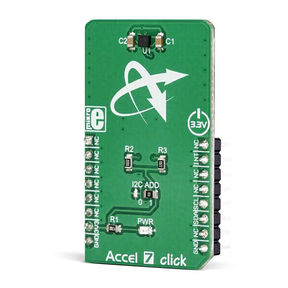
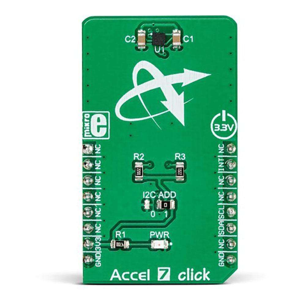
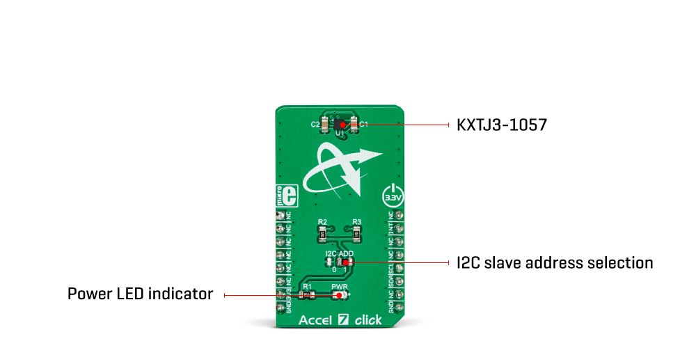
The Accel 7 Click Board™ is a tri-axis acceleration sensing Click Board™ powered by the KXTJ3-1057 14-bit tri-axis digital accelerometer from Kionix. This sensor was developed using proprietary Kionix micro-machining technology, resulting in high accuracy and excellent noise immunity. The Accel 7 Click Board™ supports a wide range of applications that require low power consumption, fast response, precision, and reliability. As such it can be used for motion detection, display orientation, HID applications, drop detection applications (for warranty logging), and similar applications that rely on acceleration and motion-sensing.
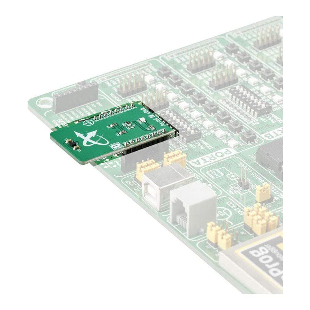
It comes in a package that also includes the mikroSDK software and a library with all the functions. The Accel 7 Click Board™ comes as a fully tested and approved prototype, making it a reliable device ready to use on the development board.
Downloads
The acceleration sensing is based on the principle of measuring the differential capacitance, which further decreases errors due to manufacturing imperfections, temperature and other environmental influences. The micro-electromechanical sensor (MEMS) is coupled with a very advanced application specific integrated circuit (ASIC), which allows the simplicity of the KXTJ3-1057 design, requiring a low number of additional external components.
Using the embedded lowpass filtering allows filtering of the abrupt changes in acceleration readings. Intelligent interrupt engine allows detection of motion, inactivity, direction, data ready event, and more. Equipped with the KXTJ3-1057 advanced acceleration sensor, this Click board™ can be used in a wide range of applications that require low power consumption, fast response, good precision, and reliability. It can be used for display orientation, HID applications, drop detection applications (for warranty logging), and similar applications that rely on the reliable acceleration and motion-sensing provided by this Click board™.
How Does The Accel 7 Click Board™ Work?
The Accel 7 Click Board™ carries the KXTJ3-1057, ±2g / ±4g / ±8g / ±16g tri-axis digital accelerometer, by Kionix. This sensor utilizes an advanced acceleration sensing method, based on the differential capacitance. The integrated MEMS, produced with the proprietary Kionix technology, is composed of two plates. One is fixed to the substrate, while the other can move freely along a single axis. The acceleration causes the change in the capacitance between these plates, which is then processed by an integrated ASIC. The ASIC incorporates a capacitance-to-voltage amplifier which converts the differential capacitance of the MEMS sensor into an analog voltage, used as the input for the low-noise A/D converter (ADC). The integrated ASIC also contains the logic section used to set all the operational parameters of the KXTJ3-1057, such as the data rate, filter settings, interrupts, ADC resolution, and more. The ASIC also incorporates an OTP memory that contains the calibration parameters and other device-specific settings used on each power-on reset (POR) cycle.
The ADC can be operated with the resolution of 8, 12, or 14 bits. This allows power consumption to be managed, as the lower resolution typically allows less power consumption. The power consumption is also affected by the output data rate value (ODR). The ODR value above 400Hz forces the high-resolution mode (14-bits) so the power consumption rises exponentially as the ODR changes from 0.781Hz to 1600Hz. The ADC resolution, as well as the other operating parameters of the KXTJ3-1057 IC can be adjusted by using two configuration registers. Some options can only be altered while the IC operates in the Stand-by mode.
The acceleration range can be selected from ±2g to ±16g. The choice of the ADC resolution is directly related with the number of counts for a certain acceleration range. For example, using ±2g range with the 8-bit ADC resolution means that the whole range between -2g and +2g will be covered by 255 values, from -127 to +127. Therefore, the output of 127 will be equivalent of 2g acceleration (more precisely, 1.984g). The datasheet of the KXTJ3-1057 offers a comprehensive set of tables with these settings. However, the Accel 7 click comes with the library that contains simple to use functions which simplify the acceleration measurements.
The interrupt engine allows interrupt reporting on a dedicated INT pin. There are multiple interrupt status registers, allowing both combined and individual events to be read. This allows the INT pin to be used more flexible. Depending on the settings, it is possible to pulse and latch this pin. When latched, it will stay asserted until the specific register is read (INT_REL in the datasheet). Pulsed operation will produce a short pulse on this pin, but the status bits will remain set, until the INT_REL register is read. Un-latched mode allows the status bits to be cleared automatically, so there is no need to read the INT_REL register.
One distinctive feature of the KXTJ3-1057 is that it can generate a Wake-up (motion detection) interrupt, when the acceleration measurement exceeds the value stored in the Wake-up threshold registers. In this case, a bit in the interrupt status register will indicate that a Wake-up event occurred. The Wake-up interrupt features a debouncing counter: if an acceleration value has exceeded the threshold and remained above this threshold during a programmed number of counts, an interrupt event will be reported. To distinguish between two successive movement events, there is yet another countdown timer, which sets the non-activity time interval before another Wake-up event can be reported. Note that the thresholds use fixed g-range and resolution, regardless of user settings.
Each KXTJ3-1057 device is factory calibrated, and its calibration parameters are stored in the one-time programmable memory (OTP). These parameters include the gain corrections and offset calibration. After each POR cycle, these calibration values are automatically applied, reducing the output error. Along with the used MEMS differential sensing technology, this reduces the measurement error to a virtually unmeasurable value. A built-in self-test function allows reliable operation of the Accel 7 Click Board™.
SPECIFICATIONS
| Type | Acceleration,Motion |
| Applications | It can be used for display orientation, HID applications, drop detection applications (for warranty logging), and similar applications that rely on reliable acceleration and motion-sensing. |
| On-board modules | KXTJ3-1057, a ±2g / ±4g / ±8g / ±16g tri-axis digital accelerometer, by Kionix |
| Key Features | The MEMS is produced using the proprietary Kionix micromachining technology, resulting in a high accuracy and reliability of the acceleration measurements, reducing the influence of the production imperfections. The differential capacitance architecture of the MEMS further reduces the influence of external factors, allowing the sensor to be used in noisy environments |
| Interface | I2C |
| Compatibility | mikroBUS |
| Click board size | M (42.9 x 25.4 mm) |
| Input Voltage | 3.3V |
PINOUT DIAGRAM
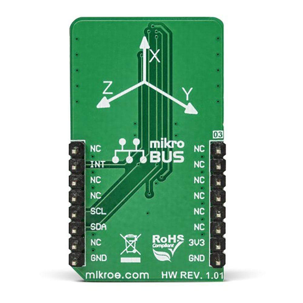
This table shows how the pinout on Accel 7 Click corresponds to the pinout on the mikroBUS™ socket (the latter shown in the two middle columns).
| Notes | Pin |  |
Pin | Notes | |||
|---|---|---|---|---|---|---|---|
| NC | 1 | AN | PWM | 16 | NC | ||
| NC | 2 | RST | INT | 15 | INT | Interrupt | |
| NC | 3 | CS | RX | 14 | NC | ||
| NC | 4 | SCK | TX | 13 | NC | ||
| NC | 5 | MISO | SCL | 12 | SCL | I2C Clock | |
| NC | 6 | MOSI | SDA | 11 | SDA | I2C Data | |
| Power supply | 3.3V | 7 | 3.3V | 5V | 10 | NC | |
| Ground | GND | 8 | GND | GND | 9 | GND | Ground |
ONBOARD SETTINGS AND INDICATORS
| Label | Name | Default | Description |
|---|---|---|---|
| LD1 | PWR | - | Power LED indicator |
| JP1 | I2C ADD | Right | I2C slave address LSB selection: left position 0, right position 1 |
ACCEL 7 CLICK ELECTRICAL SPECIFICATIONS
| Description | Min | Typ | Max | Unit |
|---|---|---|---|---|
| Acceleration measurement range | ±2 | - | ±16 | g |
| Output refresh rate (ODR) | 0.781 | - | 1600 | Hz |
| A/D Conversion resolution | 8 | - | 14 | bit |
| General Information | |
|---|---|
Part Number (SKU) |
MIKROE-3244
|
Manufacturer |
|
| Physical and Mechanical | |
Weight |
0.019 kg
|
| Other | |
Country of Origin |
|
HS Code Customs Tariff code
|
|
EAN |
8606018713899
|
Warranty |
|
Frequently Asked Questions
Have a Question?
Be the first to ask a question about this.

