


Mikroelektronika d.o.o.
SigFox Click Board™ (UK & Europe)
SigFox Click Board™ (UK & Europe)
SKU: MIKROE-2534
Couldn't load pickup availability
Overview
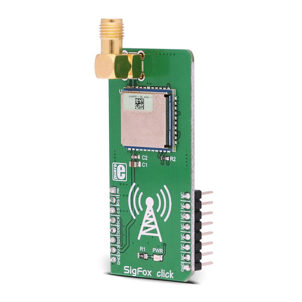
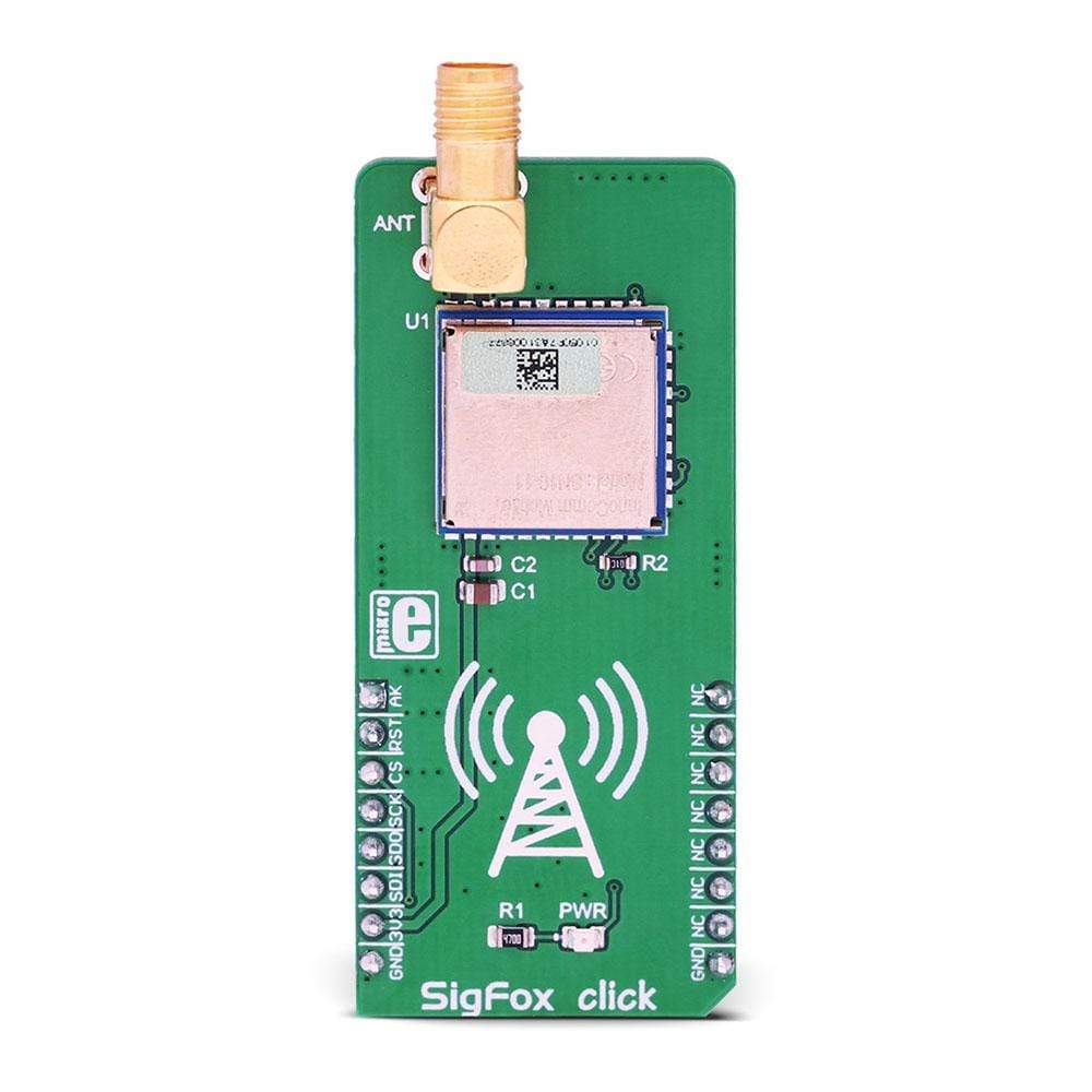
The SigFox Click Board™ is a device that carries the SN10-11, a fully integrated Sigfox certified module by InnoComm, allowing connection to a low power wide area network (LPWAN) that enables communication utilizing the Industrial, Scientific, and Medical (ISM) radio frequency band.
The SigFox Click Board™ comes with a subscription to the Sigfox network for a duration of one year from the moment of Activation.
It comes in a package including the mikroSDK software and a library with all the functions. The Click Board™ comes as a thoroughly tested and approved prototype, making it a reliable device ready to use on the development board.
Note: Sigfox Click Board™ is intended to be used in the RCZ1 (OK and Europe region).
Downloads
Activate your Sigfox Click Board™ by using the ID and PAC numbers which you can find on the package box of your SigFox Click board™.
- See the Sigfox Coverage page to view radio presence in the whole world, and the name of all local Sigfox Operators.
- For a full updated list of supported regions and their radio configurations (RCZ) please visit Sigfox radio configuration page.
- Learn about the next steps for setting up the Sigfox connection.
How Does The SigFox Click Board™ Work?
The Sigfox network is a star topology network, specifically designed for the Internet of Things (IoT) applications. It uses an ultra-narrow frequency band, able to penetrate through the objects and cover large distances, making it a perfect choice for various industry-specific applications, such as the sensors networking in agriculture.
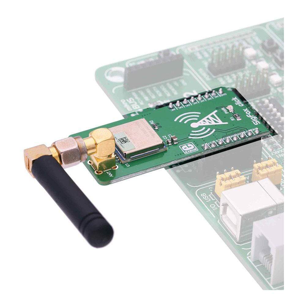
The SigFox Click Board™ offers all that is needed to integrate a Sigfox network connectivity into a design. Besides the SN10-11 module itself, it offers the industry-standard SPI communication protocol and an onboard SMA connector, used to connect the appropriate 868MHz antenna. With its low power consumption, SigFox click can be used on a battery-operated platform for a very long time, without replacing the battery.
The SigFox Click Board™ is equipped with the SN10-11 Sigfox™ certified module, manufactured by InnoComm Mobile Technology Corporation. The hearth of this module is the OL2385, a sub-GHz wireless transceiver System-on-Chip (SoC). The communication between the SN10-11 module and the host MCU is performed over the SPI. An additional AK pin is used to signal the command acknowledgment. There is a number of commands available, which are all sent in a specific format. Each data packet transferred via the SPI bus contains the number of bytes to be sent, the command itself, and the data payload (if there is one). Upon the successful command, the AK pin will indicate the response. This pin is routed to the mikroBUS™ AN pin.
In addition, commands return the status over the SPI. If a command is successful, a status of 0 is returned, for example. Different status responses have different meaning. Some commands may return various error codes, indicating a certain condition of the signal chain. For example, a command might get accepted by the module, but refused by the remote base station (station not reachable, and similar). All the commands are a part of the firmware API offered by the module, over the SPI interface. However, the library which comes with the SigFox click contains functions that encapsulate all the necessary commands and handle the responses, offering simplified programming interface, in the familiar MikroElektronika compilers environment.
The module can be reset over the RST pin of the mikroBUS™. This pin is pulled to a HIGH logic level internally. Setting it to a LOW logic level will perform a hardware reset of the SN10-11 module.
The Sigfox network operates using a public frequency bandwidth, defined by the regional radio regulations, such as the ERC-REC-70-3E for the EU region, for example. In the EU region, the Sigfox network operates at 868MHz. This network is a star topology type of network and requires a base station which collects the data from the connected nodes and sends it to the Sigfox cloud for further processing and distribution.
The nodes can be as far as 1000m from the base station, depending on the regional Sigfox network frequency (the official information about the network coverage can be found on the Sigfox site). Node objects can be various temperature and humidity sensors, parking lot sensors, etc. The node objects communicate with the base using the Differential Phase Shift Keying (DPSK) communication method. Small messages with the data payload as low as 12 bytes are transmitted several times per day, allowing conservative power consumption. The ultra-narrow frequency band allows the TX power to stay really low, saving even more power and allowing batteries to last a few years. This is very well suited for various industrial applications, such as the agriculture industry, where many sensor nodes are often scattered over a wide area and are hard to reach for a frequent battery replacement.
Once it collects the data, a base station will decode it and send it to the Sigfox cloud. The data is processed and pushed back to the user application. While the uplink (information transfer from the node to the cloud) is performed using the more robust and efficient DPSK communication method, the downlink (information transfer from the cloud to the application) uses the Frequency Shift Keying (FSK), which is less robust than the DFSK and uses broader frequency range. Typically, the interference is not a big concern for the downlink. The key difference between similar, cellular network based IoT network solutions, is that all stations in range will pick up the node signal and forward it to the cloud, not just a single station.
The Sigfox cloud is unique and all the base stations are connected to it. This type of centralized approach can have some inherited benefits. For example, it is possible to track goods, by accessing data sent by another station in a different part of the country, or even a different country. With its global Low Power Wide Area network, Sigfox is a true Internet of Things.
Specifications
| Type | Sigfox,Sub-1 GHz Transceievers |
| Applications | The SigFox Click Board™ offers connectivity to the SigFox network. It can be used for a wide range of IoT applications, which require large area coverage, such as the agriculture industry applications, parking lot applications, goods tracking applications, and similar |
| On-board modules | SN 10-11 Sigfox certified module, by InnoComm |
| Radio Region | Europe |
| Key Features | Official Sigfox network certified module onboard, simplified software functions allow rapid development, robust IoT networking with very wide area coverage, Sigfox cloud allows access to distant base stations and nodes, and more |
| Interface | SPI |
| Compatibility | mikroBUS |
| Click board size | L (57.15 x 25.4 mm) |
| Input Voltage | 3.3V |
Pinout diagram
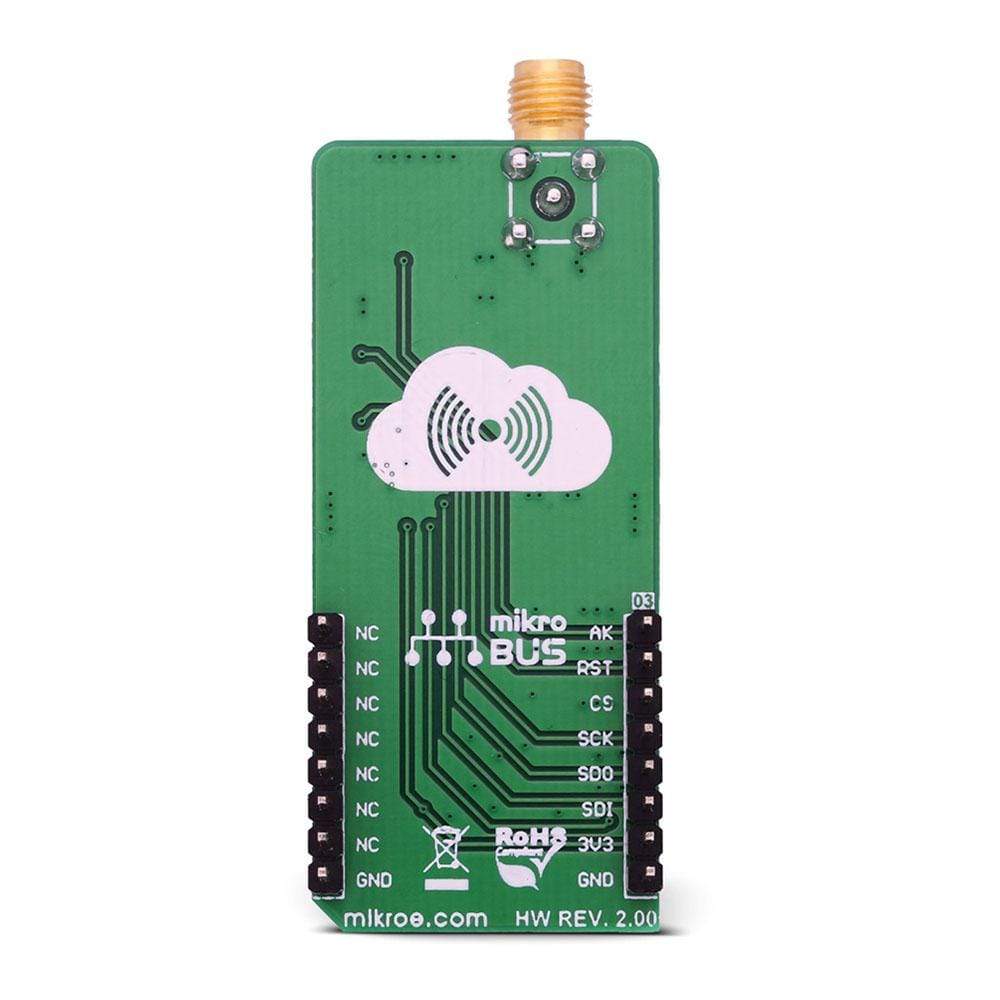
This table shows how the pinout on the SigFox Click Board™ corresponds to the pinout on the mikroBUS™ socket (the latter shown in the two middle columns).
| Notes | Pin | Pin | Notes | ||||
|---|---|---|---|---|---|---|---|
| ACK OUT | AK | 1 | AN | PWM | 16 | NC | |
| Reset | RST | 2 | RST | INT | 15 | NC | |
| Chip Select | CS | 3 | CS | RX | 14 | NC | |
| SPI Clock | SCK | 4 | SCK | TX | 13 | NC | |
| SPI Data OUT | SDO | 5 | MISO | SCL | 12 | NC | |
| SPI Data IN | SDI | 6 | MOSI | SDA | 11 | NC | |
| Power supply | 3.3V | 7 | 3.3V | 5V | 10 | NC | |
| Ground | GND | 8 | GND | GND | 9 | GND | Ground |
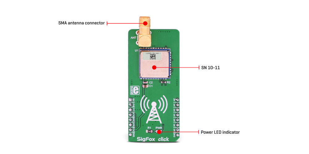
Onboard connectors and indicators
| Label | Name | Description |
|---|---|---|
| PWR | PWR | Power LED indicator |
| ANT | ANT | SMA antenna connector |
| General Information | |
|---|---|
Part Number (SKU) |
MIKROE-2534
|
Manufacturer |
|
| Physical and Mechanical | |
Weight |
0.019 kg
|
| Other | |
EAN |
8606018713509
|
Frequently Asked Questions
Have a Question?
Be the first to ask a question about this.