Overview
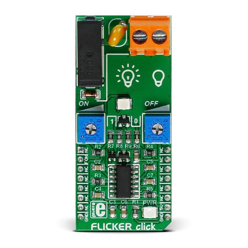
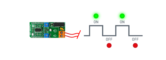
Thanks to the onboard NA556 dual precision timer from Texas Instruments and the G6D-ASI power PCB relay from Omron, the FLICKER Click Board™ can control loads up to 5A, 250 VAC/30 VDC at a predefined time interval.
The on/off period can last from 0.1 to 6 seconds, which can be set by the two ON/OFF onboard potentiometers. The external load can be connected to the board through the screw terminal. FLICKER Click Board™ runs on a 5V power supply and it communicates with the MCU over the RST pin.
Downloads
FLICKER Click Board™
Thanks to the onboard NE556DR dual precision timer from Texas Instruments and the G6D-ASI power PCB relay from Omron, the FLICKER Click Board™ can control loads up to 5A, 250 VAC/30 VDC at a predefined time interval.
The on/off period can last from 0.1 to 6 seconds, that can be set by the two ON/OFF onboard potentiometers. The external load can be connected to the board through the screw terminal. The FLICKER Click Board™ runs on 5V power supply and it communicates with the MCU over RST pin.
 DO NOT TOUCH THE BOARD WHILE THE EXTERNAL POWER SUPPLY IS ON!
Note: The FLICKER Click Board™ has exposed pins/pads. To stay safe take precaution when applying high voltage to the click. The click is to be used by trained personnel only when applying high voltage.
Applications
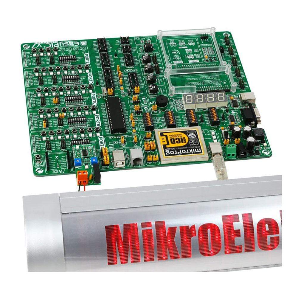
The FLICKER Click Board™ is the perfect, simple solution if you need to turn a device on and off at specific time intervals, like blinking LED commercials, alarm system lights, or any other signaling lights.
SPECIFICATIONS
| Type | Relay |
| Applications | The FLICKER Click Board™ is the perfect, simple solution if you need to turn a device on and off at specific time intervals, like blinking LED commercials, alarm system lights, or any other signalling lights |
| On-board modules | NA556 dual precision timer from Texas Instruments and the G6D-ASI power PCB relay from Omron |
| Key Features | G6D-ASI power PCB relay, Max. loads up to 5 A, 250 VAC/30 VDC, Min. permissible load 10 mA at 5 VDC, Contact resistance 100 mΩ max |
| Interface | GPIO |
| Compatibility | mikroBUS |
| Click board size | L (57.15 x 25.4 mm) |
| Input Voltage | 5V |
PINOUT DIAGRAM
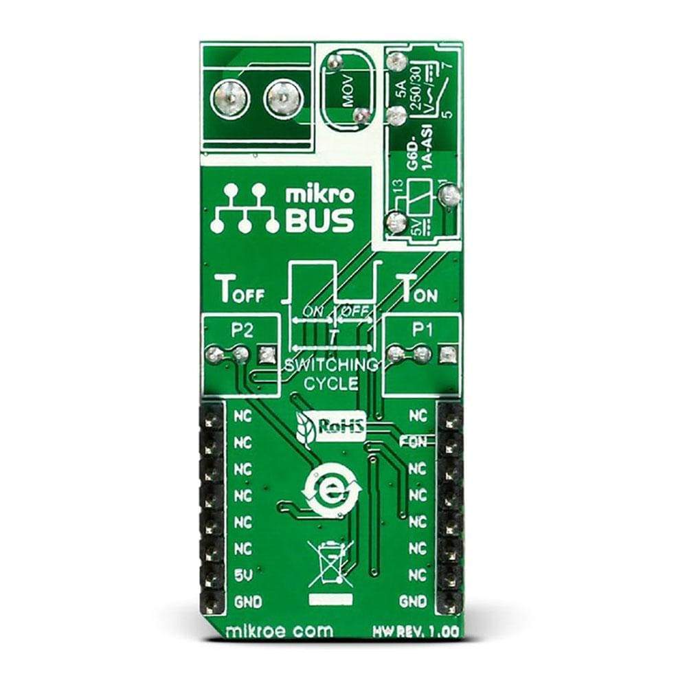
This table shows how the pinout of the FLICKER Click Board™ corresponds to the pinout on the mikroBUS™ socket (the latter shown in the two middle columns).
| Notes | Pin |  |
Pin | Notes | |||
|---|---|---|---|---|---|---|---|
| NC | 1 | AN | PWM | 16 | NC | ||
| Turns the NE556 on and off | FON | 2 | RST | INT | 15 | NC | |
| NC | 3 | CS | RX | 14 | NC | ||
| NC | 4 | SCK | TX | 13 | NC | ||
| NC | 5 | MISO | SCL | 12 | NC | ||
| NC | 6 | MOSI | SDA | 11 | NC | ||
| NC | 7 | +3.3V | +5V | 10 | +5V | +5V power supply | |
| Ground | GND | 8 | GND | GND | 9 | GND | |
ONBOARD PCB RELAY
Maximum switching capacity of the G6D-ASI PCB relay is 1250VA at 150W. Maximum contact resistance is 100 mΩ.
POTENTIOMETERS
The two potentiometers (P1 and P2) set the switching on and off time.
| Designator | Name | Type | Description |
|---|---|---|---|
| P1 | Potentiometer | Adjusting Ton | |
| P2 | Potentiometer | Adjusting Toff | |
| CN1 | Terminal block | Connector | for connecting the device |
MAXIMUM RATINGS
| Description | Min | Typ | Max | Unit |
|---|---|---|---|---|
| Contact resistance | 100m | Ω | ||
| Operate time | 10m | s | ||
| Ambient temperature | -25 | 70 | C | |
| Operating current | 5 | A | ||
| Operating voltage | 250 | VAC |
| General Information | |
|---|---|
Part Number (SKU) |
MIKROE-2481
|
Manufacturer |
|
| Physical and Mechanical | |
Weight |
0.029 kg
|
| Other | |
Country of Origin |
|
HS Code Customs Tariff code
|
|
EAN |
8606015079356
|
Warranty |
|
Frequently Asked Questions
Have a Question?
Be the first to ask a question about this.

