
Key Features
Overview
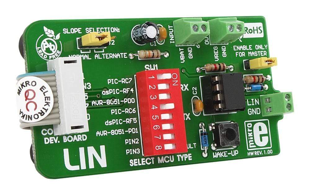
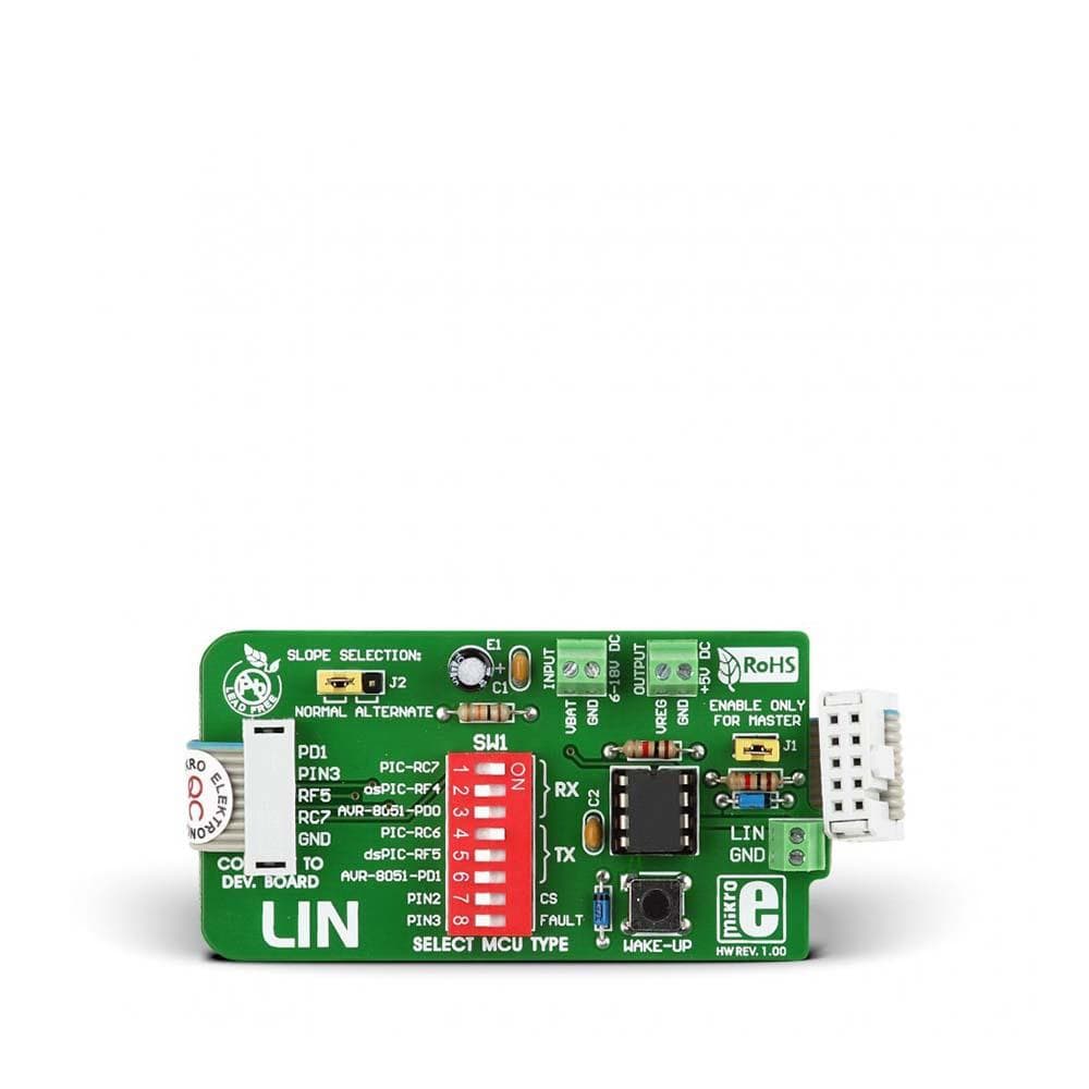
The MikroE LIN Board connects your development system to LIN (Local Interconnect Network). The board has an MCP201 LIN transceiver with a voltage regulator that supports baud rates up to 20 Kbaud. The transceiver facilitates a physical interface between an MCU and a LIN half-duplex bus. The board receives data from the development system via UART communication and converts it to be sent further through the LIN network. The board also provides a half-duplex, bi-directional communication interface between a microcontroller and a serial network bus. It converts CMOS/TTL logic levels to LIN logic levels and vice versa. It is designed to operate a 5V power supply only. This voltage can be used to power a device through another screw terminal. Using a third screw terminal, it connects to the LIN. The LIN features one master and up to 16 slave devices. It has jumpers, which are used to set master/slave mode and normal/alternate slope mode.
The LIN Board is an ideal choice for use in automotive and industrial applications.
Downloads
IC/Module: MCP201 LIN Transceiver with Voltage Regulator
The LIN Board is based on the Microchip MCP201 is a high-performance LIN transceiver that offers a physical interface between a microcontroller and a LIN half-duplex bus. With serial bus speeds up to 20 Kbaud, it makes a well-suited choice for industrial and automotive applications. It also offers a half-duplex, bidirectional communication interface between a microcontroller and the serial network bus. It will translate the CMOS/TTL logic levels to LIN level logic, and likewise from LIN level logic to CMOS/TTL logic levels.
Regulated Power Output
The MCP201 aboard the LIN Board has a +5V 50mA regulated power supply. Featuring a LDO design, this short-circuit protected regulator is designed to turn the regulator output off if it falls below 3.5 V. It also provides thermal shutdown protection.
How to Connect the LIN Board
The LIN Board uses an IDC10 connector to connect to a development system. The power supply voltage is supplied via a screw terminal CN4, which the LIN Board regulates and decrease to 5V. This voltage can be used to power a device through another screw terminal (CN3). The board can also be connected to devices sharing LIN through CN2.
| General Information | |
|---|---|
Part Number (SKU) |
MIKROE-235
|
Manufacturer |
|
| Physical and Mechanical | |
Weight |
0.1 kg
|
| Other | |
Warranty |
|
HS Code Customs Tariff code
|
|
EAN |
8606015071114
|
Frequently Asked Questions
Have a Question?
Be the first to ask a question about this.


