


OMICRON-Lab
OMICRON Lab B-WIT 100 Wideband Injection Transformer
OMICRON Lab B-WIT 100 Wideband Injection Transformer
SKU: P0005758
Payment methods
- Bank transfer
Couldn't load pickup availability


Key Features
Overview
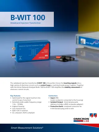
The OMICRON Lab B-WIT 100 injects a test signal into a control loop so a Bode 100 or other frequency response analyser can measure loop gain and phase margin. Usable range 1 Hz to 10 MHz, 1:1 turns ratio, insertion loss under 0.5 dB at 10 kHz, 120 pF primary-secondary capacitance, isolation rated 600 V CAT II. For loops that cross over below 1 Hz, OMICRON Lab offers the B-LFT 100.
Why Engineers Choose the OMICRON Lab B-WIT 100 Wideband Injection Transformer
Enhanced Measurement Accuracy
Safety and Compliance Assurance
Complete Frequency Coverage
The OMICRON Lab B-WIT 100 is a wideband injection transformer for loop gain and stability measurement, usable from 1 Hz to 10 MHz with a 1:1 turns ratio, under 0.5 dB insertion loss at 10 kHz and isolation rated to 600 V CAT II. It couples the source output of a Bode 100 or another frequency response analyser across an injection resistor in the control loop. Power supply designers use it to measure gain and phase margin on DC/DC converters and voltage regulators, in the lab or on a manufacturing test station.
Loop Gain Measurement From 1 Hz to 10 MHz
The usable frequency range runs from 1 Hz to 10 MHz, with a typical -3 dB range of 7 Hz to 5 MHz. Insertion loss is under 0.5 dB at 10 kHz (S21, 50 Ω termination), and the typical primary-to-secondary capacitance of 120 pF at 1 kHz keeps loading of the loop under test low. Typical volt-second capacity is 3.5 mVs and the maximum input voltage is 10 Vrms.
Injection Transformer Setup with the Bode 100
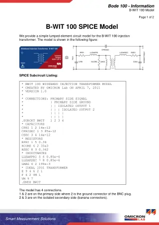
The BNC input plug connects to the source output of the analyser, such as the Bode 100. The isolated output on 4 mm safety banana jacks goes across an injection resistor placed in the feedback path. OMICRON Lab specifies a resistor of 1 Ω to 10 Ω and recommends 10 Ω. Two voltage probes pick up the signal on either side of the resistor and the analyser plots loop gain from their ratio. Because the disturbance is injected differentially, the DC operating point of the converter is not disturbed.
600 V CAT II Isolation for Off-Line Supplies
Isolation between input and output is rated to 600 V CAT II, so the injection point can sit at a high potential while the analyser stays referenced to earth. An earth terminal on the housing must be connected to safety ground whenever voltages above 30 VAC or 60 VDC are present. Maximum current is 1 A, limited by an internal fuse that is not user-replaceable.
Specifications
| Usable frequency range | 1 Hz to 10 MHz |
|---|---|
| -3 dB frequency range | 7 Hz to 5 MHz (typ.) |
| Turns ratio | 1:1 |
| Insertion loss | < 0.5 dB at 10 kHz (S21, 50 Ω termination) |
| Primary-secondary capacitance | 120 pF at 1 kHz (typ.) |
| Max. volt-second | 3.5 mVs (typ.) |
| DC saturation current | 15 mA (typ.) |
| Max. input voltage | 10 Vrms (absolute maximum, user manual) |
| Max. current | 1 A (fuse, not user-replaceable) |
| Isolation | 600 V CAT II |
| Input connector | BNC plug |
| Output connectors | 4 mm safety banana jacks (isolated), plus earth terminal |
| Recommended injection resistor | 1 Ω to 10 Ω (10 Ω recommended) |
| Dimensions | 129 x 64 x 32.5 mm (including connectors) |
| Weight | 0.25 kg |
| Operating temperature | -20 °C to +60 °C |
| Relative humidity | 5% to 80% |
| Max. altitude | 2,000 m |
Limitations
- The analyser and voltage probes are not included. The B-WIT 100 is the injection element only.
- DC saturation current is 15 mA (typ.). OMICRON Lab states that no DC signal may be applied to the output.
- Below 1 Hz, choose the B-LFT 100: its lower -3 dB point is under 100 mHz (typ.) and it injects a 1 Hz signal at the Bode 100's full 2 Vrms output without saturating, for slow loops such as PFC regulators.
- Above 10 MHz, consider the Picotest J2101A, specified for 10 Hz to 45 MHz into a 5 Ω termination.
- Do not open or modify the unit. It has no user-serviceable parts.
Injection Transformer Comparison
| Feature | B-WIT 100 | B-LFT 100 | Picotest J2101A |
|---|---|---|---|
| Frequency range | 1 Hz to 10 MHz (usable) | < 100 mHz to > 15 kHz (-3 dB, typ. 20 kHz upper) | 10 Hz to 45 MHz (5 Ω termination) |
| Turns ratio | 1:1 | 1:1 | 1:1 |
| Insertion loss | < 0.5 dB at 10 kHz | < 1 dB at 100 Hz | Not stated by Picotest |
| Isolation | 600 V CAT II | 600 V CAT II | 600 V CAT II |
| Price | €682,95 | €951,95 | €688,95 |
Typical Applications
Gain and phase margin measurement on DC/DC converter control loops with a Bode 100, using a 10 Ω injection resistor in the feedback divider path. Loop stability checks on linear voltage regulators across the 7 Hz to 5 MHz -3 dB band. Production verification of loop stability on a manufacturing test station, with the injection path isolated to 600 V CAT II and safety-rated probes.
The B-WIT 100 suits power electronics engineers who already own a frequency response analyser and need one injection transformer that spans both mid-frequency and fast switching-converter loops.
What's Included
- B-WIT 100 injection transformer
- BNC to 4 mm banana adapter
The OMICRON Lab B-WIT 100 is €682,95 ex VAT. If your loop crosses over below 1 Hz, check the B-LFT 100 first, or contact us for a formal quotation covering the analyser and probes. See all injection transformers we stock.
Last reviewed: 30 October 2026
Sources (2 manufacturer pages)
| Ordering information | |
|---|---|
| Part number (SKU) | P0005758 |
| Manufacturer | OMICRON-Lab |
| EAN | 5055383623259 |
| Warranty | 12 months |
| Shipping weight | 0.25 kg |
- 1 ×B-WIT 100 injection transformer
- 1 ×BNC to 4 mm banana adapter
Questions and Answers
-
Which Injection Resistor Should I Use with the B-WIT 100?
Between 1 Ω and 10 Ω, with 10 Ω recommended by OMICRON Lab. The resistor sits in the feedback loop and the transformer output is connected across it, so the DC operating point is unchanged.
-
Can I Measure on a Mains-Connected (Off-Line) Power Supply?
Yes, within the 600 V CAT II isolation rating. Connect the earth terminal to safety ground whenever voltages above 30 VAC or 60 VDC are present, and use safety-rated voltage probes.
-
What Is the Difference Between the B-WIT 100 and B-LFT 100 Injection Transformers?
The B-WIT 100 covers 1 Hz to 10 MHz for general-purpose use. The B-LFT 100 specialises in low-frequency work below 100 kHz, with better performance and maximum signal coupling at very low frequencies for PFC and other slow control loops.
-
Why Is a 1:1 Turns Ratio Important in Injection Transformer Design?
A 1:1 turns ratio gives unity voltage transfer while keeping galvanic isolation. Because loop gain is taken from probes on both sides of the injection resistor, the turns ratio does not affect the result.
-
How Does the B-WIT 100 Compare to the Picotest J2101A?
Compared with Picotest's J2101A (10 Hz to 45 MHz), the B-WIT 100 covers 1 Hz to 10 MHz, so it reaches lower frequencies, while the J2101A goes higher.
-
What Probe Recommendations Work Best with the B-WIT 100?
OMICRON Lab recommends its PML-111O 10:1 passive probes, and warns that standard 10:1 oscilloscope probes can damage the Bode 100 inputs. Keep capacitive loading low, use a probe with an adequate voltage rating for the circuit under test, and use proper grounding.
-
Can the B-WIT 100 Be Used with Network Analysers Other Than the Bode 100?
Yes. The B-WIT 100 has a standard BNC input and 4 mm banana jack outputs, so it works with other network analysers and frequency response analysers.
-
What Frequency Range Does the B-WIT 100 Cover and Why Is This Important?
The B-WIT 100 has a usable frequency range of 1Hz to 10MHz, with -3dB points typically at 7Hz and 5MHz. This covers slow control loops and fast switching converters with crossover frequencies in the MHz range, so one transformer covers most loops. For very slow loops such as PFC, the B-LFT 100 injects more signal at low frequencies.
-
How Does the B-WIT 100 Ensure Safety When Testing High-voltage Power Supplies?
The B-WIT 100 has 600V CAT II compliant isolation between primary and secondary windings. With its earth terminal connected to safety ground and safety-rated probes used, this galvanic separation protects the engineer and test equipment when measuring mains-voltage power supplies.
-
What Makes the B-WIT 100 Superior to DIY Injection Transformer Solutions?
The B-WIT 100 is optimised for signal injection into control loops, with high linearity and low insertion loss.
-
Can the B-WIT 100 Handle DC Current in the Injection Loop?
The brochure lists a maximum DC current of 10 mA (typical saturation 15 mA). Keep DC through the output winding low; the manual warns not to apply DC signals to the output.
-
How Does Insertion Loss Affect Control Loop Measurements?
The B-WIT 100's insertion loss is below 0.5dB at 10kHz, so it does not significantly attenuate the test signal. Keep the injection resistor small (1 to 10 Ω) to limit its effect on the loop.


No questions match your search.
