
SPI Protocol
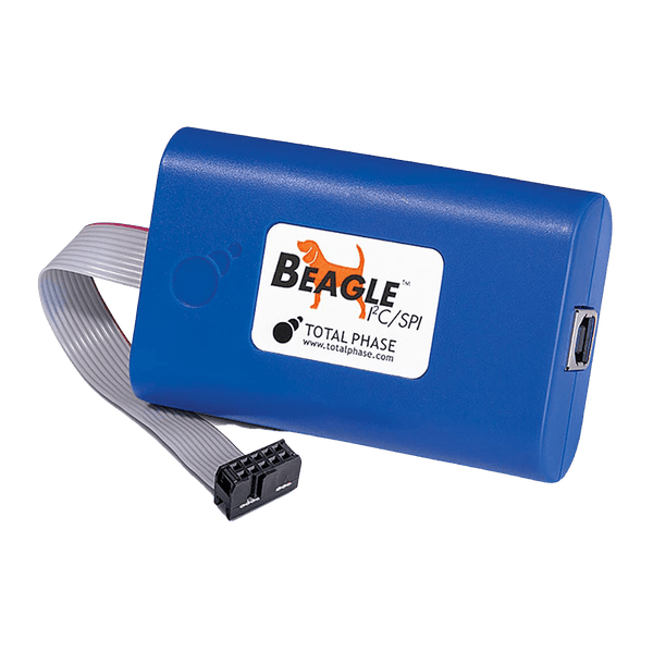
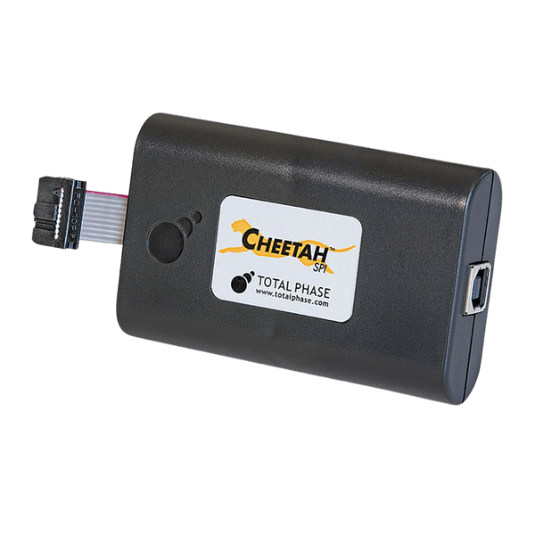
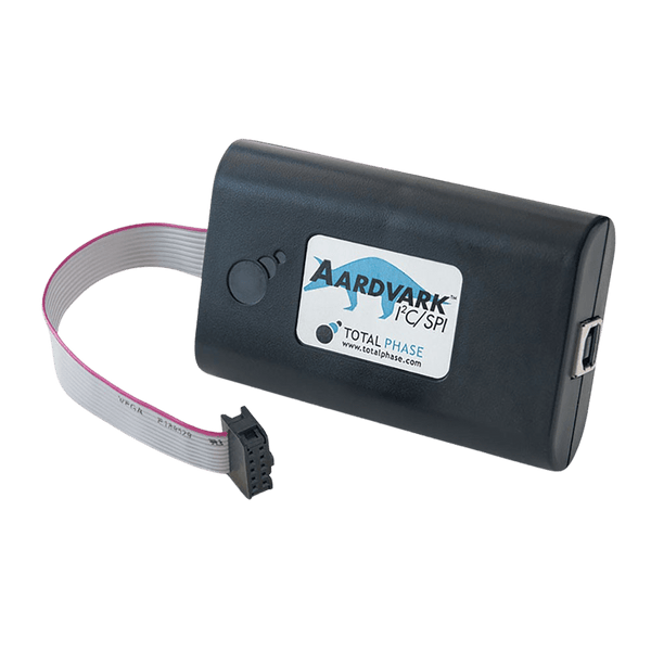
SPI (Serial Peripheral Interface) is a synchronous, full-duplex serial link between a controller and one or more targets on the same board: a clock (SCLK), a data line in each direction (COPI and CIPO, formerly MOSI and MISO) and one chip select per target. To watch a bus, use a protocol analyser such as the Beagle I2C/SPI, which monitors SPI to 24 MHz without driving it, or a logic analyser with an SPI decoder. To drive SPI devices from a PC, use a host adapter such as the Aardvark or the faster Cheetah.
How the SPI Bus Is Wired
The controller drives the clock and both outputs are actively driven high and low, so there are no pull-up resistors to size and no rise-time limit from the bus as there is on I2C. Instead of addresses, each target has its own chip select (CS, also called SS or CE), normally active low. The controller pulls one CS low, clocks the transfer, then releases it. A target whose CS is high must leave CIPO in high impedance so it does not fight the selected device.
The older names MOSI (master out, slave in) and MISO (master in, slave out) still appear on most datasheets and tools. Newer documents use SDO and SDI as seen from each device, or controller and peripheral names such as COPI and CIPO or PICO and POCI (the OSHWA recommendation). They are the same signals.
How an SPI Transfer Works
- Select: the controller pulls the target's chip select low. Many devices treat the falling edge of CS as the start of a command.
- Clock and shift: on each clock, one bit leaves the controller on COPI and one bit leaves the target on CIPO. Most devices send the most significant bit first, but check the datasheet.
- Frame: there is no length field. The number of clocks while CS is low decides how many bits move. Typical commands are a byte or two followed by address and data bytes.
- Deselect: the controller releases CS high. On many devices this is what makes a write take effect, so a CS glitch mid-transfer corrupts the command.
Because data moves both ways at once, a read is really an exchange: the controller clocks out dummy bytes to clock the answer back in.
Clock Modes
| Mode | CPOL (Clock Idle Level) | CPHA | Data Sampled On |
|---|---|---|---|
| Mode 0 | Low | 0 | Rising edge (first edge) |
| Mode 1 | Low | 1 | Falling edge (second edge) |
| Mode 2 | High | 0 | Falling edge (first edge) |
| Mode 3 | High | 1 | Rising edge (second edge) |
Controller and target must use the same mode. Mode 0 and mode 3 are the most common; many serial flash and sensor parts accept either. A mode mismatch usually shows up as every byte shifted by one bit.
Dual and Quad SPI
Serial NOR flash and some displays extend SPI by using the data lines in both directions. Dual SPI moves two bits per clock on IO0 and IO1; Quad SPI moves four on IO0 to IO3, reusing the write-protect and hold pins. The command byte is usually still sent on one line, and the flash datasheet defines which commands switch to two or four lines. Analysers and host adapters must support the wider mode to capture or generate these transfers.
Where SPI Is Used
- Boot and storage: serial NOR flash holding firmware or a BIOS, SPI EEPROMs and FRAM, SD cards in SPI mode.
- Data converters: ADCs and DACs, where full-duplex streaming at several MHz matters more than addressing.
- Displays: small TFT and OLED panels and their touch controllers.
- Sensors and radios: accelerometers, gyroscopes, pressure sensors, Ethernet controllers and sub-GHz or 2.4 GHz radio modules.
- Programming: in-system programming of SPI flash on a finished board, and loading FPGA configuration from flash.
Common SPI Faults and How to Find Them
| Symptom | Likely Cause | What to Check |
|---|---|---|
| Every byte off by one bit, or reads as 0xFF | Clock mode mismatch between controller and target | Capture SCLK and data with an analyser and compare the sampling edge with the datasheet mode |
| Reads return 0xFF or 0x00 regardless of command | Wrong chip select, CS not reaching the device, or CIPO not connected | Confirm CS goes low at the target pin during the transfer |
| Works slowly, fails at full clock rate | Long wires or a weak driver; round-trip delay on CIPO exceeds half a clock period | Look at edge quality on an oscilloscope; shorten leads or lower SCLK |
| Two targets corrupt each other | A deselected target drives CIPO instead of releasing it | With CS high, CIPO from that target should float; check for a missing tri-state |
| Flash writes do not stick | Write-enable command missing, or CS released before the command completed | Decode the command sequence: write enable, then program, then poll status |
| Quad reads garbage, single reads fine | Quad mode not enabled in the flash status register, or IO2 and IO3 held by WP and HOLD | Read the status register and check the quad-enable bit |
Tools for Analysing and Decoding SPI
Watch tools listen to an existing bus and record every transfer with timestamps. Drive tools take the place of the controller or a target, to talk to a device before the firmware exists or to script production tests and flash programming.
Protocol Analyser
| Product | Role | Capability | Price ex VAT |
|---|---|---|---|
| Total Phase Beagle I2C/SPI (TP320121) | Watch | Non-intrusive SPI monitor to 24 MHz (capture rate depends on the host PC), with I2C to 4 MHz and MDIO to 2.5 MHz on the same unit | €500,95 |
Logic Analysers with SPI Decoding
The better choice when SPI is one of several signals you need to see together, such as an interrupt or reset line, or two buses at once.
| Product | Role | Capability | Price ex VAT |
|---|---|---|---|
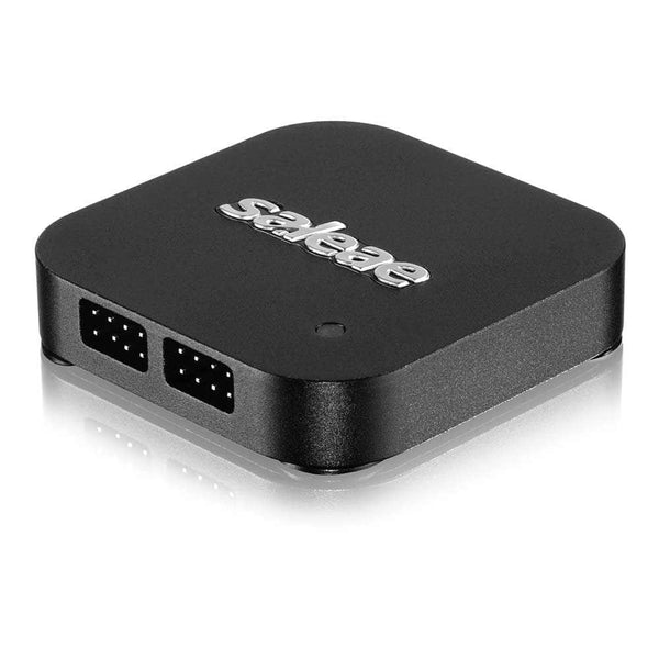
| Saleae Logic 8 | Watch | 8 channels, digital and analogue; SPI decoder in the Logic 2 software | €506,95 |
| Saleae Logic Pro 8 | Watch | 8 channels at higher sample rates; same SPI decoder | €1.038,95 |
| Saleae Logic Pro 16 | Watch | 16 channels, room to capture Quad SPI plus control lines (the built-in decoder is single SPI; a community QSPI analyser covers quad) | €1.557,95 |
Host Adapters
| Product | Role | Capability | Price ex VAT |
|---|---|---|---|
| Total Phase Aardvark (TP240141) | Drive | SPI controller 125 kHz to 8 MHz, target to 4 MHz; also I2C | €419,95 |
| Total Phase Cheetah (TP280121) | Drive | High-speed SPI controller, 0.1 MHz to 40+ MHz, up to 3 chip selects | €594,95 |
| Promira with SPI Active Level 1 (TP600510) | Drive | SPI controller to 12.5 MHz, target to 8 MHz, 1 chip select | €150,95 plus the €1.301,95 Promira |
| Promira with SPI Active Level 2 (TP600610) | Drive | Single and Dual SPI controller to 40 MHz, target to 20 MHz, up to 3 chip selects | €306,95 plus the Promira |
| Promira with SPI Active Level 3 (TP600710) | Drive | Single, Dual and Quad SPI controller to 80 MHz, target to 20 MHz, up to 8 chip selects | €1.013,95 plus the Promira |
Flash Programming and Test Targets
- Dediprog SF100 (€362,95): in-system programmer for SPI flash soldered on the board, through an ISP header or test clip.
- TP280210 High-Speed SPI Flash Demo Board (€111,95): a known-good 50 MHz SPI flash target (Winbond W25Q32JV) for the Aardvark, Cheetah, Promira and Beagle.
- TP240310 I2C/SPI Activity Board (€100,95): a known-good I2C and SPI target for learning a tool or proving a test set-up.
Browse every tool in our protocol decoders, logic analysers and host adapters collections. Not sure which fits your clock rate and voltage? Send us the target device and bus speed and we will recommend one.
Frequently Asked Questions
What Is the Difference Between SPI and I2C?
SPI uses a separate chip select per device and push-pull outputs, so it runs much faster, typically tens of MHz, and moves data both ways at once. I2C uses two shared wires with addresses and acknowledges, so it needs fewer pins and tells you when a device does not answer, but tops out at a few Mbit/s.
Which SPI Mode Should I Use?
The one in the target device datasheet. Look for the clock idle level (CPOL) and whether data is sampled on the first or second edge (CPHA). If the datasheet only shows a timing diagram, read the clock level while CS is high and the edge where data is stable.
Can SPI Have Several Controllers?
Not in normal use. SPI has no arbitration, so two controllers driving SCLK at once would collide. Systems that need it hand over control in software or through a separate signal.
How Fast Can SPI Run?
There is no protocol limit; the devices and wiring set it. Serial flash commonly runs at 50 MHz or more on a short PCB trace, while the same part on a ribbon cable to a test fixture may need a few MHz. The round-trip delay on CIPO is usually what fails first.
Do I Need a Protocol Analyser or Will a Logic Analyser Do?
A logic analyser with an SPI decoder shows commands and data alongside other signals and is enough for most bring-up work. A dedicated protocol analyser such as the Beagle I2C/SPI records long sessions as a searchable transaction list, which is faster when one bad transfer is hidden among thousands.
Where to Start with SPI
More Protocols
By John Legg CEng, Director, Debug Store. Updated 3 November 2026.
