
LPC Bus (Low Pin Count)
LPC (Low Pin Count) is the bus that connects a PC chipset to its slow peripherals: Super I/O, embedded controller, TPM, and on older boards the BIOS flash. It moves 4-bit nibbles on LAD[3:0] at 33 MHz, framed by LFRAME#. Serial IRQ carries the peripherals' interrupts on one more wire. On a board that will not boot, decoding LPC shows the POST codes the BIOS writes to port 80h and every access to the Super I/O and TPM. Newer platforms replace LPC with eSPI.
How an LPC Cycle Works
- START: the host pulls LFRAME# low and drives a START code on LAD. 0000 starts a normal target cycle; 1101 and 1110 start firmware hub reads and writes.
- Cycle type and direction: I/O read or write, memory read or write, or DMA. Bus master cycles are signalled by their own START codes.
- Address: four nibbles for a 16-bit I/O address, eight nibbles for a 32-bit memory address, most significant nibble first.
- Data: on a write, the host sends the byte low nibble first.
- Turnaround and SYNC: after two turnaround clocks the target drives SYNC: 0000 for ready, 0101 or 0110 for short or long wait (repeated while it is busy), 1010 for an error. On a read, the data follows SYNC.
Serial IRQ and Firmware Hub
SERIRQ replaces the dedicated interrupt lines of ISA with a single wire clocked by LCLK. A frame contains a start sequence, then one slot of three clocks per signal (IRQ0 to IRQ15, with SMI# in the IRQ2 slot, then IOCHCK# and the PCI INTA# to INTD# interrupts), then a stop sequence. A peripheral signals its interrupt by driving the line low in its slot. In quiet mode the line idles between frames; a peripheral that needs to report an interrupt starts a frame by pulling SERIRQ low for one clock, and the host completes it. Firmware Hub (FWH) devices sat on the same LAD pins and held the BIOS before SPI flash took over that job.
Where LPC Is Used
- PC and server motherboards: Super I/O chips (serial ports, PS/2, hardware monitoring), embedded controllers in laptops, and the TPM security chip.
- Industrial and embedded x86 boards: many still use LPC to legacy I/O controllers and FPGAs.
- Debug: POST code cards read port 80h writes from the LPC bus to show how far the BIOS got.
- BMCs: server management controllers that emulate Super I/O and keyboard controller functions on LPC.
Common LPC Faults and How to Find Them
| Symptom | Likely Cause | What to Check |
|---|---|---|
| Board stops during boot | BIOS waiting on a device, or a device returning errors | Decode port 80h writes to see the last POST code, then the cycles that follow it |
| Super I/O not detected | Device never answers with SYNC, or answers at the wrong I/O address | Look for cycles to the configuration ports (2Eh/2Fh or 4Eh/4Fh) and the SYNC reply |
| Long boot delays | Device holding long wait SYNCs | Count wait SYNC nibbles per cycle in the capture |
| Lost or spurious interrupts | SERIRQ in the wrong mode, or a device driving the wrong slot | Decode the SERIRQ frame and check which slot goes low |
| TPM errors | TPM not responding within the expected timing, or locality register access failing | Decode memory cycles to the TPM address range (FED40000h onwards) |
Tools for Analysing and Decoding LPC
Watch tools capture LAD[3:0], LFRAME#, LCLK and SERIRQ and decode them into cycles. At 33 MHz, either sample at 200 MS/s or more, or use the analyser's state mode with LCLK as the external clock, which captures exactly one sample per bus clock and makes long captures practical.
| Product | Role | Capability | Price ex VAT |
|---|---|---|---|
| ZeroPlus LAP-C Pro Series | Watch | Logic analyser with LPC, LPC-SERIRQ and FWH protocol analysis | €1.157,95 |
| ZeroPlus LAP-F 40/64-Channel | Watch | 40 or 64 channels with the same decoders, for LPC plus SPI flash and reset lines together | €1.689,95 |
| Acute TravelLogic 34-Channel | Watch | Logic analyser running Acute's decoder library, which includes LPC and Serial IRQ | €1.453,95 |
| Acute LA4000 Series | Watch | 68 or 136 channels at higher sample rates for full platform bring-up; same decoder library | €8.883,95 |
For the replacement bus on current Intel and AMD platforms, see our eSPI guide; for the BIOS flash itself, see SPI. Tell us the platform and what you need to trigger on and we will recommend a set-up.
Frequently Asked Questions
What Replaced LPC?
eSPI (Enhanced Serial Peripheral Interface). It runs at 1.8 V on fewer pins and carries peripheral cycles, virtual wires, out-of-band messages and flash access over one link. Intel platforms began moving to eSPI around 2015 and AMD platforms some years later, though many boards kept LPC.
How Do I Read POST Codes From LPC?
Capture LAD, LFRAME# and LCLK with an LPC decoder and filter for I/O writes to address 0080h. The data byte is the POST code. Some platforms also use other ports, so check the BIOS documentation.
Is LPC the Same as ISA?
LPC was designed to replace ISA on motherboards. It carries the same kinds of cycles (I/O, memory, DMA) so legacy software keeps working, but on seven signals instead of dozens.
What Sample Rate Do I Need?
For timing (asynchronous) capture at 33 MHz, 200 MS/s or more. For decoding long boot sequences, state mode clocked by LCLK is better: one sample per clock, so memory goes much further.
What Is SERIRQ Quiet Mode?
In continuous mode the host starts a SERIRQ frame regularly. In quiet mode the line stays idle until a peripheral needs to report an interrupt, when it pulls SERIRQ low for one clock and the host completes the start of the frame. The host sets the mode with the length of the stop pulse at the end of each frame.
Where to Start with LPC and Serial IRQ
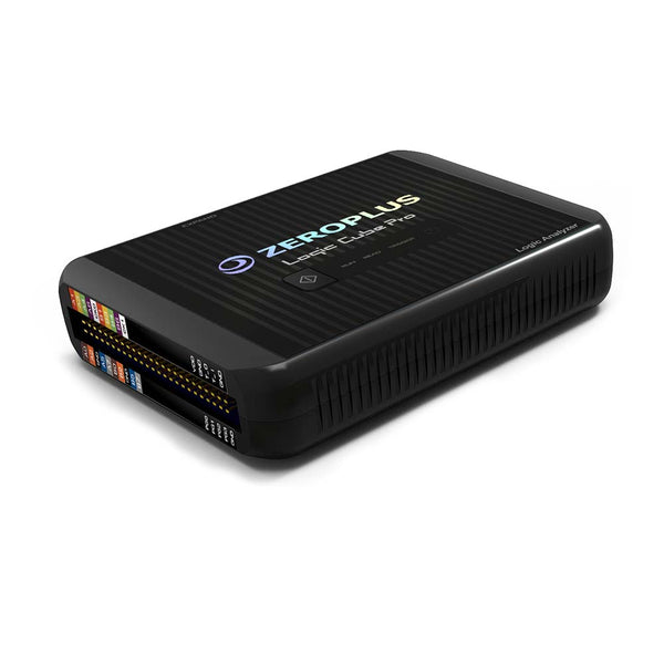 ZeroPlus LAP-C Pro Series Logic Analyser
From €1.157,95
ex VAT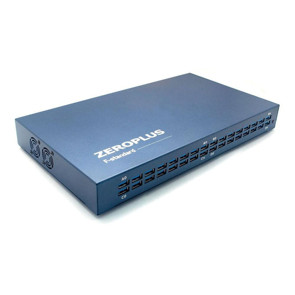 ZeroPlus LAP-F High-Performance PC-Based Logic Analyser 40/64 Channel
€1.689,95
ex VAT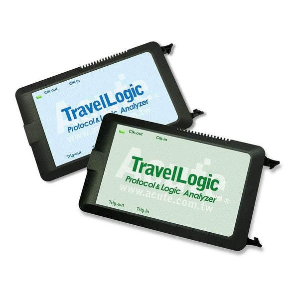 Acute Technology TravelLogic 34-Channel Logic Analyser
From €1.453,95
ex VAT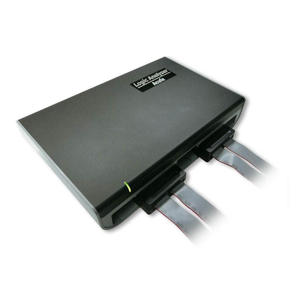 Acute Technology LA4000 Series 68/136 Ch Logic Analyser
From €8.883,95
ex VAT
More Protocols
By John Legg CEng, Director, Debug Store. Updated 12 November 2026.
