
eSPI Protocol
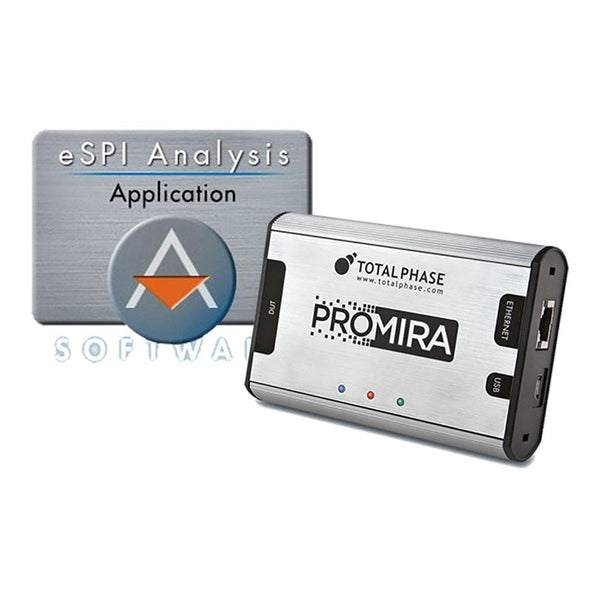
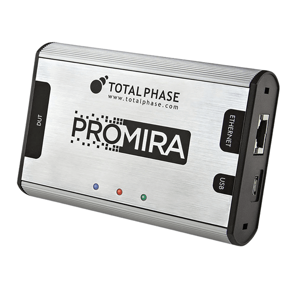
eSPI (Enhanced Serial Peripheral Interface) is the Intel-defined bus that links a PC or server chipset to its embedded controller, BMC or Super I/O, replacing the older LPC bus: a clock and two or four IO lines (single, dual or quad IO) at 1.8 V and up to 66 MHz, carrying four logical channels over one link. To capture and decode it, use the Promira eSPI Bus Analyser Kit, which monitors all four channels in single, dual and quad IO without driving the bus.
How the eSPI Bus Is Wired
The chipset or SoC is the controller. It drives the clock and shares the IO lines with each target, and each target has its own chip select. Targets use an ALERT# line, or an in-band alert on IO1 when only one target is present, to ask the controller to poll them, because only the controller can start a transaction. A reset line holds the eSPI interfaces in a known state while the platform powers up.
Electrically, eSPI looks like Quad SPI at 1.8 V. Pin counts drop compared with LPC mainly because sideband signals travel as in-band virtual wire messages. Logically, it is very different: every transfer is a packet with a CRC, the target always answers with a status word, and the channel number tells the receiver what kind of traffic it is.
The Four eSPI Channels
| Channel | What It Carries | Replaces |
|---|---|---|
| Peripheral | I/O and memory cycles to the target, such as the embedded controller's ports and ACPI registers | LPC I/O and memory cycles |
| Virtual wire | Sideband signals sent as messages: sleep states, platform reset, SMI and SCI events, interrupts | Dedicated GPIO and sideband pins |
| Out-of-band (OOB) | SMBus-style messages tunnelled between the chipset and the target, for example for a BMC | Separate SMBus links |
| Flash access | Shared access to the system SPI flash, from controller to target or target to controller depending on the flash sharing mode | Separate flash wiring to the EC |
How an eSPI Transaction Works
- Select: the controller pulls one chip select low. Only one target is selected at a time.
- Command phase: the controller sends an opcode that names the channel, a header giving the cycle type, tag and length, any data, and a CRC.
- Turn-around: two clocks while the IO lines change direction.
- Response phase: the target answers with a response code (accept, defer, wait states or error), any data, a status word showing which of its queues have traffic waiting, and a CRC.
- Deselect: chip select returns high. If the status shows pending data, the controller follows up with a read of that channel.
After reset the link starts in single IO at 20 MHz. The controller reads each target's capabilities and then raises the clock and IO width, so a capture from power-on shows the configuration being negotiated before normal traffic.
Where eSPI Is Used
- Laptops and desktops: the embedded controller that handles the keyboard, battery, fans, lid switch and power sequencing talks to the chipset over eSPI.
- Servers: the BMC uses eSPI for host communication, virtual wires and, often, access to the host's boot flash.
- Industrial and embedded x86 boards: Super I/O chips for legacy serial ports, hardware monitoring and watchdogs.
- Firmware development: BIOS and EC teams bringing up power sequencing, sleep states and flash sharing.
Common eSPI Faults and How to Find Them
| Symptom | Likely Cause | What to Check |
|---|---|---|
| Platform hangs early in boot | The target never completes the capability exchange, or answers with an error | Capture from reset and read the configuration cycles and response codes |
| Sleep or wake fails | A virtual wire such as a sleep-state or platform reset indication is missing or sent in the wrong order | Filter the virtual wire channel and compare the sequence with the platform design guide |
| Intermittent CRC errors | Signal integrity at the chosen clock and IO width | Check whether errors stop at a lower frequency or single IO; probe edges with a scope |
| EC cannot read the shared flash | Flash sharing mode set differently on the chipset and the EC | Decode the flash access channel and confirm which side issues the requests |
| Long stalls between transactions | Target answering with repeated wait or defer responses | Look at response codes and timestamps to see which cycles are deferred |
Tools for Analysing and Decoding eSPI
Watch tools listen to the link between the chipset and its targets and decode every packet. Because eSPI runs at 1.8 V and up to 66 MHz in quad IO, a general-purpose logic analyser needs a dedicated eSPI decoder and enough sample rate to be useful; a protocol analyser built for eSPI is the practical choice.
| Product | Role | Capability | Price ex VAT |
|---|---|---|---|
| Total Phase Promira eSPI Bus Analyser Kit | Watch | Promira platform with the eSPI Analysis application: monitors 20 to 66 MHz in single, dual and quad IO; decodes peripheral, virtual wire, OOB and flash channels; two chip selects, two alert lines and two reset lines | €2.664,95 |
| eSPI Analysis Application (TP601010) | Watch | The same eSPI analysis licence, for a Promira you already own | €1.520,95 plus the Promira |
The Promira also runs I2C and SPI analysis and host applications, so one unit, with the right licences, can also monitor SMBus and SPI flash traffic up to 40 MHz on the same board. See the full Total Phase I2C, SPI and eSPI tools range, or ask us which licences fit your platform.
Frequently Asked Questions
What Is the Difference Between eSPI and SPI?
eSPI reuses the SPI pins and quad IO signalling at 1.8 V, but adds packets, CRCs, response codes and four logical channels. A plain SPI decoder will show the bits but not the transactions; you need an eSPI-aware decoder.
Why Did eSPI Replace LPC?
LPC needs a 33 MHz, 3.3 V, 4-bit multiplexed bus (7 required pins, up to 13 in all) plus separate sideband signals. eSPI runs at 1.8 V, carries those sideband signals as virtual wires, and adds out-of-band and flash access channels, so the chipset needs fewer pins.
Can a Logic Analyser Decode eSPI?
Only with enough sample rate for a 66 MHz clock and a decoder that understands eSPI packets and channels. For bring-up and debugging, a dedicated eSPI analyser shows transactions, response codes and channel traffic directly.
What Clock Speed Does eSPI Start At?
After reset, eSPI starts in single IO mode at 20 MHz. The controller then reads the target capabilities and switches to the agreed frequency and IO width.
Where to Start with eSPI

More Protocols
By John Legg CEng, Director, Debug Store. Updated 3 November 2026.
