
CAN Bus and CAN FD (ISO 11898)
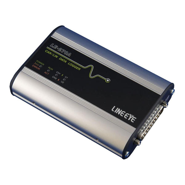
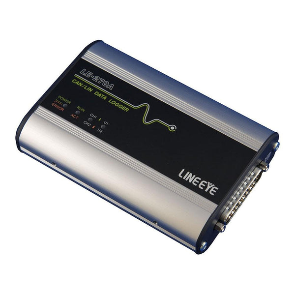
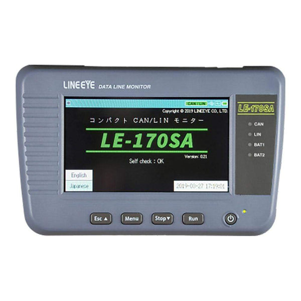
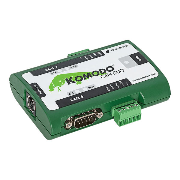
CAN (Controller Area Network) is a multi-master serial bus on one twisted pair, defined in ISO 11898, that lets ECUs, sensors and controllers broadcast short messages with built-in priority and error handling: classical CAN runs up to 1 Mbit/s with up to 8 data bytes per frame, and CAN FD raises that to 64 bytes with a faster data phase. To capture and decode it, use a CAN analyser such as the Lineeye LE-270AF logger, the handheld LE-170SA, or the Total Phase Komodo CAN Duo, which can also transmit as a node.
How a CAN Bus Is Wired
Every node connects to the same two wires through a CAN transceiver. The bus is a line, not a star: a 120 Ω resistor at each end matches the cable impedance and stops reflections, so a correctly terminated bus measures about 60 Ω between CAN_H and CAN_L with the power off. Stubs to each node are kept short. Nodes have no addresses; each message carries an identifier that says what it is, and every node decides for itself whether to use it.
The dominant and recessive levels are what make CAN arbitration work. If two nodes start sending at once, each one reads the bus as it transmits. A node sending a recessive 1 that sees a dominant 0 knows it has lost, stops, and tries again after the frame ends. The winner never notices, so the highest-priority message gets through with no lost time.
How a CAN Frame Works
- Start of frame: one dominant bit synchronises every node.
- Arbitration: the identifier (11 bits standard, 29 bits extended) and the RTR bit. Lower identifiers have higher priority.
- Control: the IDE bit marks standard or extended format, and the 4-bit data length code gives the number of data bytes.
- Data: 0 to 8 bytes in classical CAN.
- CRC: a 15-bit checksum and a delimiter.
- Acknowledge: the sender leaves the ACK slot recessive; any node that received the frame correctly drives it dominant. No acknowledgement means nobody received it.
- End of frame: seven recessive bits, then a gap before the next frame.
Every node checks every frame. A node that detects an error sends an error frame, which destroys the frame for everyone, and the sender retries. Each node keeps transmit and receive error counters: a node that keeps causing errors becomes error passive, and eventually goes bus-off and stops transmitting, so one faulty node cannot block the bus.
CAN, CAN FD and LIN Compared
| Classical CAN | CAN FD | LIN | |
|---|---|---|---|
| Payload | 0 to 8 bytes | 0 to 64 bytes | 1 to 8 bytes |
| Speed | Up to 1 Mbit/s | Arbitration up to 1 Mbit/s, data phase faster (often 2 to 5 Mbit/s) | Up to 20 kbit/s |
| Access | Multi-master, arbitration | Multi-master, arbitration | One commander, schedule-driven |
| Wiring | Twisted pair, terminated | Twisted pair, terminated | Single wire plus ground |
| Typical use | Powertrain, body, industrial | ADAS, gateways, flashing ECUs | Seats, mirrors, switches, sensors |
A CAN FD controller can talk to classical CAN frames, but a classical CAN controller treats a CAN FD frame as an error, so mixed networks need care. See the LIN page for the low-cost sub-bus that often hangs off a CAN ECU.
Where CAN Is Used
- Vehicles: powertrain, chassis and body networks, and OBD-II diagnostics on cars and light commercial vehicles.
- Trucks, buses and agricultural machinery: SAE J1939 and ISOBUS run on CAN.
- Industrial automation: CANopen and DeviceNet for drives, I/O modules and sensors.
- Medical, marine and lift equipment: anywhere a low-cost multi-drop bus with built-in error handling is needed in an electrically noisy environment.
Common CAN Faults and How to Find Them
| Symptom | Likely Cause | What to Check |
|---|---|---|
| No communication, constant error frames | Missing or extra termination | With power off, measure CAN_H to CAN_L: about 60 Ω is correct, 120 Ω means one terminator is missing, 40 Ω means one too many |
| Frames sent but never acknowledged | Only one node on the bus, or every other node at a different bit rate | Check that at least one other node is powered and set to the same bit rate; an analyser in listen-only mode does not acknowledge |
| Node goes bus-off | Bit rate or sample point mismatch, or a wiring fault on that node | Capture error frames and error counters; compare bit timing settings across nodes |
| Intermittent errors at high load | Long stubs or poor cable, reflections | Look at edges on a scope; shorten stubs; check the cable impedance |
| A message never gets through | Its identifier keeps losing arbitration to higher-priority traffic | Measure bus load and the gaps between frames with an analyser |
Tools for Analysing and Decoding CAN
Watch tools listen and decode every frame with timestamps. Drive tools also transmit, to simulate a missing ECU or test how a node responds. Check whether you need CAN FD, how many channels, and whether the tool must log on its own in a vehicle without a PC.
CAN and CAN FD Analysers and Loggers
| Product | Role | Capability | Price ex VAT |
|---|---|---|---|
| Lineeye LE-270AF CAN/LIN Data Logger | Watch Drive | Two channels, each CAN, CAN FD (data phase 1 to 5 Mbit/s) or LIN; logs to SD card without a PC or streams to a PC over USB (Wi-Fi where enabled for the country of shipment); four analogue or digital inputs; test transmission of registered frames | €1.244,95 |
| Lineeye LE-270GF CAN/LIN Data Logger | Watch Drive | As the LE-270AF, plus GPS position and a 3-axis accelerometer logged with the bus traffic | €1.407,95 |
| Lineeye LE-170SA CAN/LIN Line Monitor | Watch Drive | Handheld with 4.3 inch touch screen: one CAN channel (20 kbit/s to 1 Mbit/s, classical CAN) and one LIN channel; triggers, search and simulation of up to 16 frames; battery powered | €1.457,95 |
| Total Phase Komodo CAN Duo Interface | Watch Drive | Two independent, galvanically isolated CAN channels to 1 Mbit/s (classical CAN); acts as a node or a non-intrusive monitor; API for Windows, Linux and macOS | €813,95 |
Multi-Protocol Analysers with a CAN Board
| Product | Role | Capability | Price ex VAT |
|---|---|---|---|
| Lineeye LE-3500XR(V2) | Watch | Multi-protocol analyser; add a CAN FD expansion board below for CAN, CAN FD and LIN alongside its serial interfaces | €2.089,95 |
| Lineeye LE-2500XR(V2) | Watch | Same analyser and the same expansion boards; serial speeds to 1.544 Mbit/s (3.15 Mbit/s on the LE-3500XR), without Modbus decoding or the program-mode simulation | €1.463,95 |
| Lineeye OP-SB7XL Expansion Kit | Watch Drive | Two channels of CAN, CAN FD (data phase to 5 Mbit/s) or LIN; monitor and simulation | €644,95 |
| Lineeye OP-SB7XC Expansion Kit | Watch Drive | CAN, CAN FD and CXPI, for body networks that use CXPI in place of LIN | €656,95 |
Logic Analysers and Oscilloscopes with CAN Decoding
| Product | Role | Capability | Price ex VAT |
|---|---|---|---|
| Saleae Logic 8 | Watch | CAN decoder in the Logic 2 software; probe the receive pin of a transceiver, or CAN_L or CAN_H against ground (tick Inverted for CAN_H) | €506,95 |
| Saleae Logic Pro 8 | Watch | Higher digital and analogue sample rates (500 MS/s and 50 MS/s, against 100 MS/s and 10 MS/s on the Logic 8), to see bit timing and edges as well as decoded frames | €1.038,95 |
| Micsig TO Series tablet oscilloscope | Watch | CAN decoding as standard, so you can check signal quality and frames on one screen | From €650,95 |
Accessories
- Total Phase CAN Bus Split Cable (€62,95): breaks out a DB-9 CAN connection for probing or joining a second device.
- Total Phase CAN Bus Terminator (€50,95): a 120 Ω terminator for a bench bus.
- Total Phase CAN/I2C Activity Board Pro (€218,95): a known-good CAN node that broadcasts its switch and sensor data (on input changes, or every 100 ms with the SEL1 jumper set) for practice and tool testing.
Browse every tool in our protocol decoders collection, or tell us your bit rate, CAN FD needs and whether you log in a vehicle, and we will recommend one.
Frequently Asked Questions
Why Does a CAN Bus Need Two 120 Ω Resistors?
The resistors match the impedance of the twisted pair at each end, so signals do not reflect back along the cable, and they pull the bus back to the recessive state between bits. One at each end gives about 60 Ω across the bus.
What Is the Difference Between CAN and CAN FD?
CAN FD keeps the same arbitration but allows up to 64 data bytes and can switch to a faster bit rate for the data phase. A classical CAN controller cannot receive CAN FD frames and will flag them as errors.
Can a Logic Analyser Decode CAN?
Yes. Probe the RX pin of a transceiver, or one bus wire against ground (tick Inverted for CAN_H), set the bit rate and use the CAN decoder. A logic analyser cannot transmit or acknowledge frames, so for simulation or active testing use a CAN interface such as the Komodo or a Lineeye analyser.
Why Are My Frames Never Acknowledged?
At least one other node must receive the frame correctly to drive the ACK slot. If the only other device is an analyser in listen-only mode, or the other nodes are at a different bit rate, the sender sees no acknowledgement and keeps retrying.
What Is the Maximum Length of a CAN Bus?
It depends on the bit rate, because a bit must reach the far end and back within one bit time. As a guide, about 40 m at 1 Mbit/s and several hundred metres at 125 kbit/s, depending on cable and transceivers.
Where to Start with CAN
More Protocols
By John Legg CEng, Director, Debug Store. Updated 3 November 2026.
