

Picotest
Picotest VRTS3-Demoboard für verteilte Systeme V1.0
Picotest VRTS3-Demoboard für verteilte Systeme V1.0
SKU: VRTS3
Verfügbarkeit für Abholungen konnte nicht geladen werden
Key Features
Overview
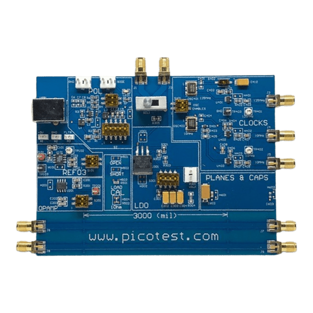
Introducing the Picotest VRTS3 Distributed System Demo Board V1.0, a versatile platform for professional design engineers and system integrators. This demo board facilitates the measurement and analysis of distributed systems, providing a clear insight into voltage and timing relationships within complex circuits. Featuring a user-friendly interface, it allows for easy configuration and real-time monitoring, enhancing your development process with visual and data-driven feedback.
Equipped with a comprehensive suite of tools, the VRTS3 board supports multiple channels for simultaneous measurements, ensuring you can efficiently analyse signal integrity, power distribution, and timing accuracy. Its compact design integrates seamlessly into existing setups, offering flexibility and precision for your engineering projects. The board comes with a detailed User Manual, which includes step-by-step instructions for setup, operation, and maintenance, ensuring optimal performance and longevity of the equipment.
Downloads
| General Information | |
|---|---|
Part Number (SKU) |
VRTS3
|
Manufacturer |
|
| Physical and Mechanical | |
Weight |
0.5 kg
|
| Other | |
EAN |
5055383624256
|
Questions and Answers
-
What Educational Advantages Does the VRTS3 Provide Compared to Expensive Dedicated Power Integrity Test Systems?
The VRTS3 lets engineers learn power integrity with their existing vector network analysers and oscilloscopes.
Its eight circuit sections represent real-world distributed system components, so you can practise Bode analysis, NISM, PSRR testing and impedance characterisation on one USB-powered board. It is used in worked examples in Picotest's probe manual.
-
How Can the VRTS3 Microstrip Section Help Engineers Understand PCB Transmission Line Effects?
The VRTS3 has 50Ω microstrips with intentional impedance aberrations, including one with a ground void (a common PCB defect that affects signal integrity).
Using TDR with the P2105A TDR Probe, you can measure velocity factor, dielectric constant and characteristic impedance, and locate discontinuities. The broken ground plane shows how discontinuities cause impedance mismatches, reflections and EMI. Measuring propagation delay, rise time degradation and reflection coefficients builds a feel for transmission line problems and how PCB layout affects power integrity.
-
What Clock Circuit Measurements Can Be Performed on the VRTS3 and Why Are They Important for Power Integrity?
The VRTS3 has 10MHz and 125MHz clock circuits for exploring how power supply noise affects clock jitter.
Clock jitter (timing variation in signal edges) directly affects high-speed digital circuits, SerDes interfaces and ADC performance. You can measure clock jitter, rise time and jitter sensitivity with an oscilloscope or spectrum analyser.
Injecting noise into the clock power rails shows power supply rejection and PDN impedance resonance coupling. Comparing the two clock frequencies shows why flat, low PDN impedance is essential.
-
How Does the VRTS3 Parallel Capacitor and Plane Section Aid in Understanding Power Distribution Network Resonance?
This section has parallel tantalum and ceramic capacitors on a PCB plane, showing parallel capacitor resonance and PDN impedance behaviour.
When capacitors of different values are paralleled, their equivalent series inductances (ESL) and resistances (ESR) interact, creating resonances that sharply raise PDN impedance at specific frequencies. With 1-port measurements using the P2104A Probe and a vector network analyser, you can measure the impedance profile and see the resonant peaks.
This shows how ESR damps resonances, how ESL sets the resonant frequency and why capacitor selection matters. Plane impedance measurements show transmission line behaviour with resonances.
-
What Makes the VRTS3 an Essential Tool for Mastering Power Supply Rejection Ratio (PSRR) Measurements?
The VRTS3 lets you practise PSRR measurement, which quantifies how well a regulator rejects input noise.
Its switching regulator, linear regulator and voltage reference let you compare PSRR across architectures. Inject modulation with the J2111B Current Injector or J2120A Line Injector, then measure input and output to calculate PSRR across frequency.
-
What Is the Picotest VRTS3 Distributed System Demo Board and What Measurements Does It Support?
The Picotest VRTS3 is a USB-powered training board with eight circuit sections for power integrity measurements using standard test equipment. It includes:
- 2.8MHz switching regulator
- 2.5V voltage reference
- operational amplifier buffer
- LD1086 linear regulator
- 10MHz and 125MHz clock circuits
- calibration ports (Short-Open-Load and 1Ω)
- parallel capacitors on a PCB plane
- 50Ω microstrips with intentional aberrations
It supports over 20 measurement types, including impedance analysis, Bode plots, non-invasive stability measurement (NISM), PSRR testing, jitter analysis, TDR measurements and EMI evaluation.
-
How Does the VRTS3 Enable Non-invasive Stability Measurement (NISM) and Why Is This Important?
NISM lets you assess voltage regulator stability without breaking the feedback loop, and the VRTS3 gives you several circuit sections to practise it on.
NISM derives phase margin from output impedance measurements, made with a Picotest current injector such as the J2111B and a vector network analyser. Unlike traditional Bode measurements, which need the loop broken, it works on fully operating circuits. That makes it the only practical option for fixed voltage regulators and integrated point-of-load converters where the feedback loop is inaccessible.
-
Which Picotest Signal Injectors Are Compatible with the VRTS3 and What Are Their Applications?
These Picotest injectors work with the VRTS3:
- J2100A Injection Transformer (1Hz-5MHz): Bode plot analysis of PFC regulators
- J2101A Injection Transformer (10Hz-45MHz): Bode plot analysis of the latest switching regulators
- J2111B Current Injector: DC-40MHz, for output impedance, PSRR and NISM measurements
- J2110A Solid State Injector: DC to 100MHz (-3dB) with low distortion
The J2100A and J2101A use 5Ω termination for minimal loop impact.
-
What PDN Probes Work with the VRTS3 and How Do They Compare to Traditional Oscilloscope Probes?
The VRTS3 works with Picotest's transmission line PDN probes, the P2102A 2-Port Probe and P2104A 1-Port Probe. Unlike traditional passive probes, they hold a constant 50Ω impedance across their frequency range, and the P2104A supports >6GHz bandwidth.
Input capacitance is very low (<1pF, typically 420fF), so loading is minimal. The "browser" design allows quick point-to-point measurements without soldering. Both probes have interchangeable heads and come in a choice of attenuations selected at purchase, and work with vector network analysers and oscilloscopes.
-
How Does the VRTS3 Calibration Section Improve Measurement Accuracy and What Standards Does It Support?
The VRTS3 has dedicated calibration ports for Short-Open-Load (SOL) calibration before testing: precision test points for short, open and 50Ω load, plus a 1Ω calibrator for use with a 2-port probe. This is essential for accurate milliohm-level impedance measurements in power distribution networks.
After the three-step SOL calibration, measure the 1Ω resistor to confirm the setup is accurate. The board supports 1-port and 2-port shunt-through measurements. Picotest gives typical ranges of 0.5Ω to 2.5kΩ (1-port reflection) and 25µΩ to 25Ω (2-port shunt-through).


No questions match your search.