


Picotest
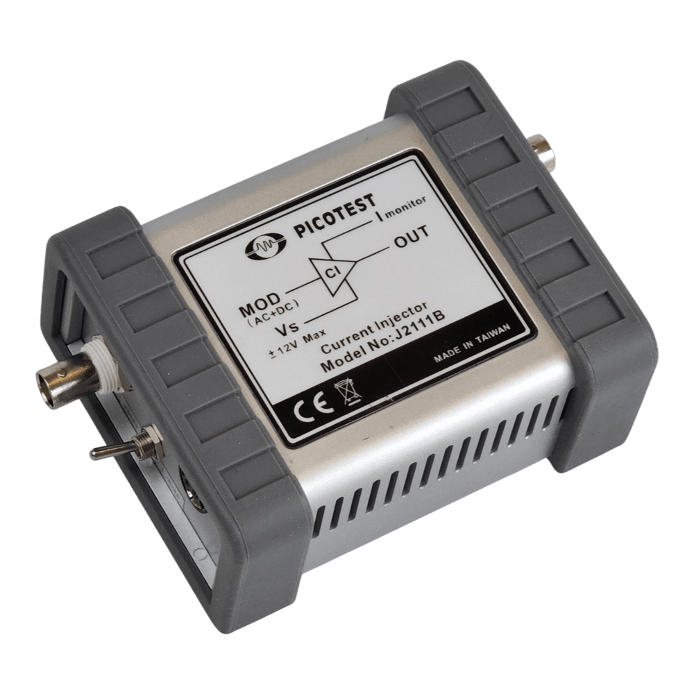
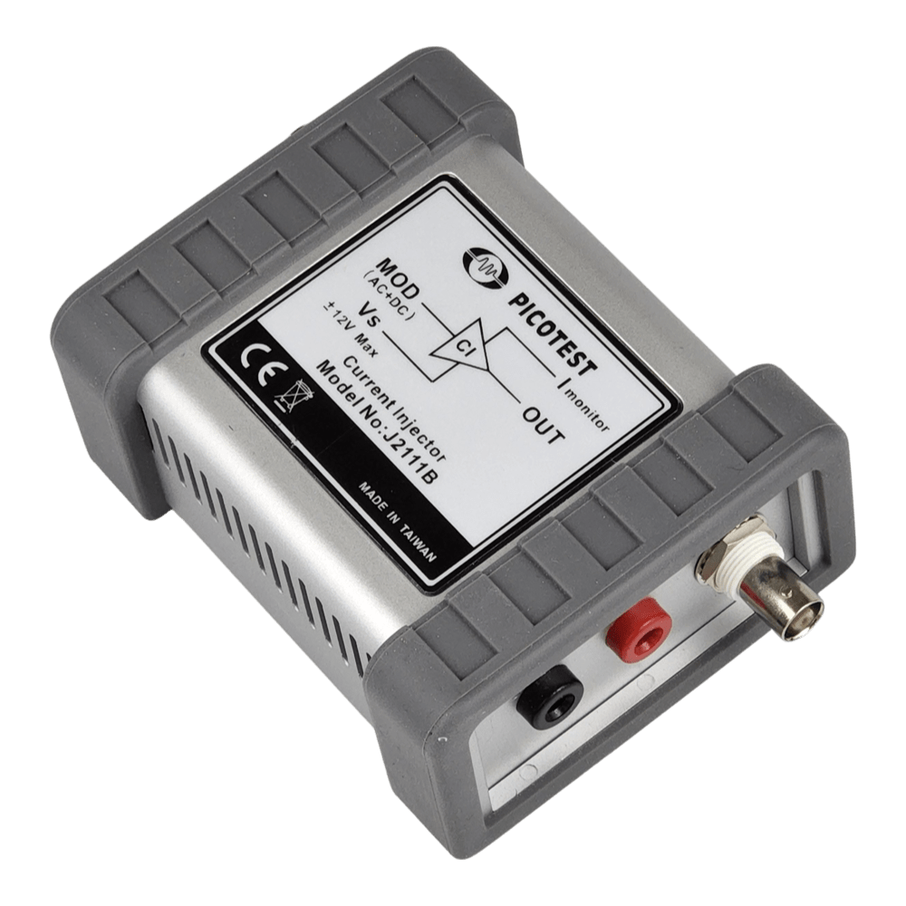
Picotest J2111B Current Injector
Picotest J2111B Current Injector
SKU: J2111B
Verfügbarkeit für Abholungen konnte nicht geladen werden
Key Features
Overview
The Picotest J2111B Current Injector stands as the most versatile tool in the signal injector family, combining bidirectional operation with 40 MHz bandwidth for comprehensive power supply characterisation. Designed for engineers who demand precision, it transforms vector network analysers and oscilloscopes into complete power integrity test systems. The J2111B sinks current from positive or negative voltage sources, making it suitable for everything from 1.8 V mobile processors to 48 V automotive systems.
Pair the J2111B with the Picotest G5100A Arbitrary Waveform Generator to generate load step waveforms with controlled rise/fall times, simulating real-world digital circuit loading. Alternatively, connect to a Bode 100 Vector Network Analyser for swept impedance measurements and Non-Invasive Stability Measurement (NISM) analysis. The built-in bias current enables Class A operation with network analysers, eliminating the need for external DC sources.
Three-port impedance measurements become straightforward: inject current through the J2111B, monitor current via the 50 Ω output, and measure voltage with a probe. The analyser calculates impedance as voltage divided by current (V/I), revealing resonances, control loop bandwidth, and damping characteristics that determine system stability and transient response.
Downloads
Why Engineers Choose The Picotest J2111B Current Injector
Bidirectional Capability
True Non-Invasive Testing
NISM Phase Margin Analysis
High-Bandwidth Current Injection for Power Integrity Analysis
The Picotest J2111B Current Injector delivers uncompromising performance for power supply output impedance measurement, non-invasive stability testing, and high-speed load transient analysis. Engineered for demanding applications where precision matters, this voltage-controlled current sink operates from DC to 40 MHz with typical rise and fall times of 20 nanoseconds, enabling accurate characterisation of modern switching regulators, LDOs, and PDN architectures.
Bidirectional Operation for Maximum Versatility
Unlike unipolar alternatives, the J2111B features two-quadrant operation, sinking current from either positive or negative voltage sources. This bipolar capability supports testing across voltage ranges from +1.5 V to +60 V and -1.5 V to -60 V, accommodating everything from low-voltage point-of-load regulators to automotive and industrial power systems. The controllable output current variation spans 50 mA, with an additional ±25 mA DC offset providing a total range of 74 mA peak.
Built-In Current Monitoring and 50 Ω Integration
A precision current monitor output delivers 1 V per amp scaling into 50 Ω, integrating seamlessly with vector network analysers, oscilloscopes, and DMMs. The modulation input accepts signals from arbitrary waveform generators (such as the Picotest G5100A), function generators, or network analysers. With 10 mA/V voltage-to-current scaling (40 dB attenuation), the J2111B enables precise control of injected current profiles for load step testing, PDN impedance sweeps, and control loop stability analysis.
Three-Port Impedance Measurement
When paired with a voltage probe and network analyser, the J2111B facilitates three-port impedance measurements, calculating output impedance as the voltage-to-current ratio (V/I). This technique proves invaluable for measuring regulator output impedance, battery impedance, and power bus characterisation. The method works particularly well for voltages ≥12 V where the 25 mA bias current represents a minor perturbation.
| Parameter | Specification | Unit |
|---|---|---|
| Output Current Variation (Controllable) | 50 | mA |
| Total Output Current (Controllable + Bias) | 74 | mA |
| Modulator Gain | 10 | mA/V |
| Current Monitor Scaling | 1 | V/A |
| Usable Bandwidth | DC–40 | MHz |
| Rise/Fall Time (Typical) | 20 | ns |
| Absolute Output Voltage Range | -60 to -1.5, +1.5 to +60 | V |
| Max Input Voltage (DC+AC) | ±5 | V |
| Offset Current (Typical) | +24/0/-24 | mA |
| Modulation Input Impedance | 50 | Ω |
| Current Monitor Output Impedance | 50 | Ω |
| Operating Temperature | 0–50 | °C |
| Maximum Altitude | 6000 | ft |
| Absolute Maximum Voltage | <50 VAC, 75 VDC | — |
Non-Invasive Stability Measurement (NISM)
The J2111B enables Non-Invasive Stability Measurement, a technique that derives phase margin from output impedance data when traditional Bode plot access is unavailable. NISM proves particularly valuable for fixed-output LDOs, voltage references, and integrated POLs where feedback pins are inaccessible. When used with OMICRON Lab Bode 100 or Keysight E5061B analysers, NISM software converts impedance measurements into phase margin values accurate to within 1 degree of traditional control loop analysis.
High-Speed Load Transient Testing
Traditional electronic loads suffer bandwidth limitations, capacitive loading, and slow slew rates. The J2111B overcomes these constraints with minimal output capacitance and 20 nanosecond edges. Drive the injector with arbitrary waveforms to simulate battery discharge profiles, high-speed digital load currents, or spontaneous current spikes. The fast response reveals regulator behaviour under transient conditions that conventional e-loads cannot replicate, exposing stability margins, underdamped ringing, and voltage droop.
Power Supply and Included Accessories
The J2111B ships with the J2171A High PSRR Regulated Adapter, a purpose-designed universal input power supply (100–240 VAC). Unlike generic switching adapters that introduce ripple above 100 kHz, the J2171A employs discrete linear regulators with ultra-high power supply rejection ratio and exceptionally low output impedance at 40 MHz. This ensures the measurement noise floor remains uncompromised by supply-induced artefacts.
Comparison: J2111B vs J2112A
| Feature | J2111B | J2112A |
|---|---|---|
| Maximum Current Output | 75 mA (50 mA + 25 mA bias) | 1 A (240 mA minimum) |
| Voltage-to-Current Scaling | 10 mA/V | 200 mA/V |
| Polarity | Bidirectional (positive/negative) | Unipolar (positive only) |
| Voltage Range | -60 to -1.5 V, +1.5 to +60 V | +0.7 to +50 V |
| Bandwidth | DC–40 MHz | DC–50 MHz |
| Rise/Fall Time | 20 ns (typical) | 10 ns (typical) |
| Current Monitor Scaling | 1 V/A | 0.1 V/A |
| Best For | Low-current, bipolar supplies | High-current POL regulators |
Applications Beyond Power Supplies
The J2111B extends to transistor characterisation, extracting small-signal current gain, transition frequency (Ft), and dynamic parameters. In RF and instrumentation circuits, it provides constant-current biasing for Class A amplifiers and buffers. Battery impedance measurement benefits from the injector's ability to sink current without introducing significant capacitive loading, preserving the accuracy of electrochemical impedance spectroscopy.
Safety and Compliance
Absolute maximum ratings must be observed at all times to avoid equipment damage or injury. Ensure output voltage remains within -60 to -1.5 V or +1.5 to +60 V. Between -1.5 V and +1.5 V, the J2111B will not operate reliably. For full specification compliance, maintain output voltage above 1.5 V or below -1.5 V. Never exceed 50 VAC or 75 VDC on the output terminals.
Questions and Answers
-
What Is the Difference Between the J2111B and J2112A Current Injectors?
J2111B J2112A Maximum current 75 mA (50 mA + 25 mA bias) 1 A (24 mA minimum) Direction Bidirectional, positive or negative supplies Sources current, positive supplies only Voltage range -60 to +60 V +0.7 to +50 V Choose the J2111B for low-current, bipolar applications. Choose the J2112A for high-current POL regulators.
-
How Do Interconnection Parasitics Affect High-frequency Measurements?
At 40 MHz, even short wires add enough inductance to roll off measurement bandwidth. Use short, low-inductance coax or wide PCB traces, and keep connections under 10 cm where possible.
The quoted 20 ns rise/fall time and 40 MHz bandwidth depend on the interconnection. For best results, place the J2111B close to the device under test.
-
Can the J2111B Test Switching Regulators and DC-DC Converters?
Yes. The J2111B can:
- Measure switching regulator output impedance, revealing control loop bandwidth, output capacitor ESR/ESL and stability margins
- Run load transient tests with arbitrary waveforms to characterise voltage droop, recovery time and undershoot/overshoot
- Derive phase margin from output impedance with non-invasive stability measurement (NISM), without breaking the feedback loop
- Measure input filter stability in combination with the converter's negative resistance
-
What Voltage Range Limitations Should I Observe?
The J2111B operates from -60 to -1.5 V and +1.5 to +60 V. Between -1 V and +1 V the J2111B does not operate reliably, so keep the output beyond ±1.5 V for full specification. Never exceed the absolute maximum ratings of 50 VAC or 75 VDC. Always check the device under test voltage before connecting.
-
How Does the J2111B Support Transistor Characterisation?
Connect the transistor collector/drain to the J2111B output, apply bias, and inject AC current while monitoring voltage. This reveals small-signal current gain (hfe or β), transition frequency (Ft), output impedance and dynamic parameters.
The 40 MHz bandwidth captures behaviour well into the RF region, useful for amplifier design and modelling.
-
What Distinguishes the J2111B From Traditional Electronic Loads?
The J2111B has 40 MHz bandwidth with 20 ns rise/fall times, far beyond typical electronic loads. Its minimal output capacitance avoids loading the circuit under test. The current monitor has 1 V/A scaling that connects directly to a vector network analyser, enabling swept impedance measurements that conventional loads can't make.
-
Can the J2111B Measure Battery Impedance?
Yes. The J2111B sinks current without adding significant capacitive loading. Connect the battery to the output terminals, inject a swept AC signal, and monitor voltage and current to calculate impedance.
-
How Does Non-Invasive Stability Measurement (NISM) Work?
NISM derives phase margin from output impedance measurements when a traditional Bode plot isn't possible.
- The J2111B injects current while monitoring output voltage.
- NISM software analyses impedance magnitude and phase, finding the impedance peak that correlates with control loop bandwidth.
- Phase margin is computed from the peak's height and sharpness.
This is useful for fixed-output LDOs, voltage references and integrated POLs.
-
What Equipment Is Needed for a Complete Three-port Impedance Measurement?
You need:
- A vector network analyser, such as the Omicron Lab Bode 100 or Keysight E5061B
- The J2111B current injector
- A voltage probe
- Optionally, a ground loop breaker such as the Picotest J2102B
The analyser stimulus drives the J2111B input, current is monitored via the J2111B output, and voltage is measured with the probe. The analyser calculates impedance as voltage divided by current.
-
Why Is the J2171A Power Adapter Included Rather Than a Standard Supply?
Generic switching adapters add ripple above 100 kHz that passes through the op-amp's power supply rejection and degrades the J2111B noise floor. The J2171A uses discrete linear regulators with ultra-high PSRR and very low output impedance at 40 MHz. This matters most when characterising low-impedance PDNs .


No questions match your search.