Mikroelektronika d.o.o.
DIGI POT 12 Click Board
DIGI POT 12 Click Board
Couldn't load pickup availability
Key Features:
- Dual-channel, 256-position resolution, 10kΩ nominal resistance, I2C-compatible interface, nonvolatile memory stores wiper settings, 50 years of typical data retention, and more
- Based on the AD5142A - digital potentiometer from Analog Devices
- Can be used for the development of mechanical potentiometer replacements, voltage-to-current conversions, gain and offset adjustment, and many other applications
- mikroBUS: I2C Interface
The DIGI POT 12 Click Board™ is an innovative add-on board designed to revolutionize potentiometer control. With its compact size and advanced features, this board is a must-have for any electronics enthusiast or professional.
Unleash the Power of Digital Potentiometer Technology
At the heart of the DIGI POT 12 Click Board™ lies the cutting-edge AD5142A from Analog Devices. This dual-channel, 256-position nonvolatile digital potentiometer delivers unparalleled precision and performance. This board guarantees exceptional reliability and accuracy with an impressive end-to-end resistance of 10KΩ and a wiper resistance of only 40Ω.
Versatility at Your Fingertips
With the DIGI POT 12 Click Board™, you can access two digitally controlled potentiometers easily adjusted via the I2C interface. Whether you need a potentiometer or linear gain modes, this board has you covered. Say goodbye to mechanical potentiometers and embrace a more efficient and precise control solution.
Endless Possibilities for Your Projects
Unlock the full potential of your electronic projects with the DIGI POT 12 Click Board™. This versatile board is perfect for developing a wide range of applications, including:
Mechanical potentiometer replacements Voltage-to-current conversions Gain and offset adjustments And much more!Experience unrivaled control and flexibility with the DIGI POT 12 Click Board™.
Streamlined Software Development
Developing software for the DIGI POT 12 Click Board™ has never been easier. Thanks to the mikroSDK-compliant library, you have access to a comprehensive set of functions that simplify the development process. Say goodbye to complex coding and hello to efficient software development.
Ready for Immediate Integration
The DIGI POT 12 Click Board™ comes fully tested and ready to be integrated into your system. Equipped with the popular mikroBUS™ socket, this board seamlessly connects to your existing setup without any hassle. Simply plug it in and let the DIGI POT 12 Click Board™ take your projects to new heights.
Upgrade your potentiometer control today with the DIGI POT 12 Click Board™. Order now and experience the future of precision control.


How Does The DIGI POT 12 Click Board™ Work?
The DIGI POT 12 Click Board™ is based on the AD5142A, a dual-channel, 256-position nonvolatile digital potentiometer from Analog Devices. The RDAC register contents determine the resistor wiper position, that act as a scratchpad register, allowing unlimited changes of resistance settings. The scratchpad register can be programmed with any position setting using the standard I2C interface by loading the 16-bit data word. The nominal resistance of the RDAC between terminals A and terminals B (RAB) is 10KΩ with 8-bit RDAC latch data decoded to select one of the 256 possible wiper settings. When a desired position is found, this value can be stored in the onboard EEPROM memory; thus, the wiper position is always restored for subsequent power-ups. The EEPROM data can be read back, written independently, and protected by software.
This Click board™ communicates with MCU through a standard 2-Wire I2C interface and operates at Standard (100KHz) and Fast (400KHz) data transfer modes. The I2C address can be selected via the ADDR SEL jumpers with 0 selected by default. There is an RST pin for resetting the digital potentiometers RDAC registers from EEPROM, with active LOW logic. In addition, this Click board™ comes with the INDEP SEL jumper that allows you to choose between the potentiometer and the linear gain setting mode, with the potentiometer mode set by default (0).
The linear gain setting mode of operation can control the potentiometer as two independent rheostats connected at a single point. Once the jumper is set, it can not be disabled by software. In addition, there is a burst mode in which multiple data bytes can be sent to the host MCU. The Shutdown mode places the RDAC in a zero power consumption while the data in EEPROM remains. There is no polarity constraint between the B, W, and A on both terminals, but they can not be higher than the VCC (5V maximum) nor lower than the VSS (0V).
The DIGI POT 12 Click Board™ can operate with either 3.3V or 5V logic voltage levels selected via the VCC SEL jumper. This way, both 3.3V and 5V capable MCUs can use the communication lines properly. However, the Click board™ comes equipped with a library containing easy-to-use functions and an example code that can be used, as a reference, for further development.
SPECIFICATIONS
| Type | Digital potentiometer |
| Applications | It can be used for the development of mechanical potentiometer replacements, voltage-to-current conversions, gain and offset adjustment, and many other applications |
| On-board modules | AD5142A - digital potentiometer from Analog Devices |
| Key Features | Dual-channel, 256-position resolution, 10kΩ nominal resistance, I2C-compatible interface, nonvolatile memory stores wiper settings, 50 years of typical data retention, and more |
| Interface | I2C |
| Compatibility | mikroBUS |
| Click board size | M (42.9 x 25.4 mm) |
| Input Voltage | 3.3V or 5V |
PINOUT DIAGRAM
This table shows how the pinout of the DIGI POT 12 Click Board™ corresponds to the pinout on the mikroBUS™ socket (the latter shown in the two middle columns).
| Notes | Pin | Pin | Notes | ||||
|---|---|---|---|---|---|---|---|
| NC | 1 | AN | PWM | 16 | NC | ||
| Reset | RST | 2 | RST | INT | 15 | NC | |
| NC | 3 | CS | RX | 14 | NC | ||
| NC | 4 | SCK | TX | 13 | NC | ||
| NC | 5 | MISO | SCL | 12 | SCL | I2C Clock | |
| NC | 6 | MOSI | SDA | 11 | SDA | I2C Data | |
| Power Supply | 3.3V | 7 | 3.3V | 5V | 10 | 5V | Power Supply |
| Ground | GND | 8 | GND | GND | 9 | GND | Ground |
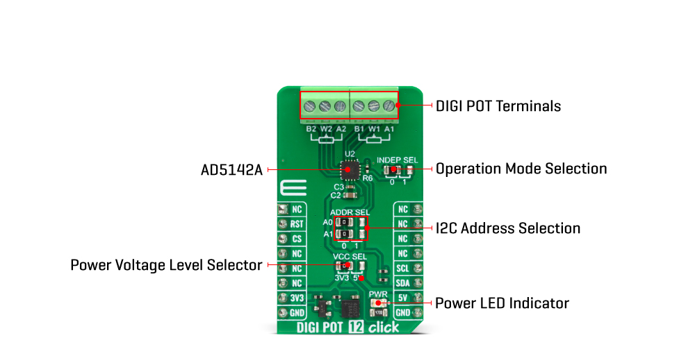
ONBOARD SETTINGS AND INDICATORS
| Label | Name | Default | Description |
|---|---|---|---|
| LD1 | PWR | - | Power LED Indicator |
| JP1 | VCC SEL | Left | Power/Logic Level Voltage Selection 3V3/5V: Left position 3V3, Right position 5V |
| JP2 | INDEP SEL | Left | Operating Mode Selection 0/1: Left position 0, Right position 1 |
| JP3-JP4 | ADDR SEL | Left | I2C Address Selection 0/1: Left position 0, Right position 1 |
DIGI POT 12 CLICK ELECTRICAL SPECIFICATIONS
| Description | Min | Typ | Max | Unit |
|---|---|---|---|---|
| Supply Voltage | 3.3 | - | 5 | V |
| Nominal Resistance | - | 10 | - | kΩ |
| Number of Taps | - | - | 256 | - |
| Resolution | 8 | - | - | bits |
Software Support
We provide a library for the DIGI POT 12 Click Board™ as well as a demo application (example), developed using MIKROE compilers. The demo can run on all the main MIKROE development boards.
The package can be downloaded/installed directly from NECTO Studio The package Manager (recommended), downloaded from our LibStock™ or found on MikroE Github account.
Library Description
This library contains API for the DIGI POT 12 Click Board™ driver.
Key functions
-
digipot12_set_resistanceDIGI POT 12 set the resistance function. -
digipot12_get_resistanceDIGI POT 12 get the resistance function.
Example Description
This library contains API for the DIGI POT 12 Click Board™ driver. The demo application uses a digital potentiometer to change the resistance values of both channels.
void application_task ( void )
 {
 static float res_kohm;
 for ( uint8_t n_cnt = DIGIPOT12_RES_0_KOHM; n_cnt <= DIGIPOT12_RES_10_KOHM; n_cnt++ )
 {
 if ( DIGIPOT12_OK == digipot12_set_resistance( &digipot12, DIGIPOT12_WIPER_SEL_1, ( float ) n_cnt ) )
 {
 if ( DIGIPOT12_OK == digipot12_get_resistance( &digipot12, DIGIPOT12_WIPER_SEL_1, &res_kohm ) )
 {
 log_printf( &logger, " Rwb1 : %.2f kOhmrn", res_kohm );
 Delay_ms( 100 );
 }
 }
 if ( DIGIPOT12_OK == digipot12_set_resistance( &digipot12, DIGIPOT12_WIPER_SEL_2, ( float ) ( DIGIPOT12_RES_10_KOHM - n_cnt ) ) )
 {
 if ( DIGIPOT12_OK == digipot12_get_resistance( &digipot12, DIGIPOT12_WIPER_SEL_2, &res_kohm ) )
 {
 log_printf( &logger, " Rwb2 : %.2f kOhmrn", res_kohm );
 Delay_ms( 100 );
 }
 }
 log_printf( &logger, " ----------------------------rn" );
 Delay_ms( 5000 );
 }
 }
The full application code, and ready to use projects can be installed directly from NECTO Studio The package Manager (recommended), downloaded from our LibStock™ or found on MikroE Github account.
Other MikroE Libraries used in the example:
- MikroSDK.Board
- MikroSDK.Log
- Click.DIGIPOT12
Additional Notes and Information
Depending on the development board you are using, you may need USB UART Click Board™, USB UART 2 Click or RS232 Click to connect to your PC, for development systems with no UART to USB interface available on the board. UART terminal is available in all MIKROE compilers.
MIKROSDK
The DIGI POT 12 Click Board™ is supported with mikroSDK - MIKROE Software Development Kit, which needs to be downloaded from the LibStock and installed for the compiler you are using to ensure proper operation of mikroSDK compliant Click board™ demo applications.
DIGI POT 12 Click Board
Frequently Asked Questions
Have a Question?
Be the first to ask a question about this.