Mikroelektronika d.o.o.
ADC 20 Click Board
ADC 20 Click Board
Couldn't load pickup availability
Key Features:
- Eight user-configurable channels, open-drain, push-pull digital outputs, wide operating ranges, SPI serial interface, high speed, high performance, high resolution, programmable averaging filters, and more
- Based on the TLA2518 - analog-to-digital converter (ADC) from Texas Instruments
- Can be used from general-purpose remote data acquisition to industrial applications
- mikroBUS: SPI Interface
The ADC 20 Click Board™: High-Performance Data Conversion Made Easy
Introducing the ADC 20 Click Board™, the compact add-on board with exceptional data conversion capabilities. With its high-performance features and reliable design, this board is perfect for various applications.
Key Features:
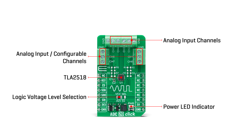
- TLA2518: The heart of the ADC 20 Click Board™ is the TLA2518, an SPI-configurable eight-channel 12-bit successive approximation register analogue-to-digital converter (SAR ADC) from Texas Instruments. Its advanced features ensure accurate and precise data conversion.
- Internal Oscillator: The TLA2518 includes an internal oscillator, simplifying the ADC conversion process and reducing the need for additional components.
- Averaging and Noise Reduction: With programmable averaging filters, the ADC 20 Click Board™ helps minimize noise from analogue inputs, delivering high-quality data. It also allows you to average multiple data samples with a single conversion start, optimizing efficiency.
- Flexible Channel Configuration: All eight ADC 20 Click Board™ channels can be used as analogue inputs. Furthermore, four channels can also serve as digital inputs or outputs, providing enhanced versatility.
Applications:
The ADC 20 Click Board™ offers outstanding accuracy, making it ideal for various applications:
- General-Purpose Remote Data Acquisition: Capture and convert data from remote sources precisely, ensuring reliable results.
- Industrial Applications: From industrial monitoring to process control, the ADC 20 Click Board™ is built to meet the demands of rugged industrial environments.
mikroSDK-Compliant Library and Seamless Integration:
To streamline your software development process, the ADC 20 Click Board™ is supported by a mikroSDK-compliant library. This library provides easy-to-use functions that simplify integration with your host MCU, reducing development time and effort.
Experience the power of the ADC 20 Click Board™ - a fully tested and ready-to-use solution designed for seamless integration with any system equipped with the mikroBUS™ socket.


How Does The ADC 20 Click Board™ Work?
The ADC 20 Click Board™ is based on the TLA2518, a small, eight-channel, multiplexed, 12-bit, 1-MSPS, analogue-to-digital converter (ADC) from Texas Instruments. The TLA2518 has an internal oscillator for the ADC conversion process and supports averaging multiple data samples with a single conversion start. Also, the built-in programmable averaging filters, which output a 16-bit result for enhanced resolution, help reduce noise from the analogue inputs and the number of data samples required to be read by the host MCU. The analogue input channel selection can be auto-sequenced to simplify the digital interface with the host MCU.
This Click board™ communicates with MCU through a standard SPI interface, supporting all four SPI-compatible protocols (SPI Mode 0, 1, 2, and 3) to access the device, and operates at clock rates up to 60MHz for all configurations and information management and acquiring conversion results. As mentioned, the TLA2518 powers up in Manual mode and can be configured into either of three operational modes by writing the configuration registers for the desired mode.
The Manual mode allows the host MCU to directly select the analogue input channel, while in the second, the On-the-Fly mode of operation, the analogue input channel is set using the first five bits on the SDI signal without waiting for the CS rising edge. This way, the ADC samples the newly selected channel on the CS edge, and there is no latency between the channel selection and the ADC output data. In the third Auto-Sequence mode, the internal channel sequencer switches the multiplexer to the next analogue input channel after every conversion.
In addition to the fact that all eight channels, also including channels on the side headers, can be used as analogue input pins, this board allows for some channels, in this case, channels CH0, CH1, CH6, and CH7 of the TLA2518 to be configured as digital inputs, open-drain digital outputs, and push-pull digital outputs.
This ADC 20 Click Board™ can operate with both 3.3V and 5V logic voltage levels selected via the VCC SEL jumper. This way, it is allowed for both 3.3V and 5V capable MCUs to use the communication lines properly. However, the Click board™ comes equipped with a library containing easy-to-use functions and an example code that can be used, as a reference, for further development.
SPECIFICATIONS
| Type | ADC |
| Applications | It can be used for general-purpose remote data acquisition to industrial applications |
| On-board modules | TLA2518 - analogue-to-digital converter (ADC) from Texas Instruments |
| Key Features | Eight user-configurable channels, open-drain, push-pull digital outputs, wide operating ranges, SPI serial interface, high speed, high performance, high resolution, programmable averaging filters, and more |
| Interface | SPI |
| Compatibility | mikroBUS |
| Click board size | M (42.9 x 25.4 mm) |
| Input Voltage | 3.3V or 5V |
PINOUT DIAGRAM
This table shows how the pinout on f the ADC 20 Click Board™ corresponds to the pinout on the mikroBUS™ socket (the latter shown in the two middle columns).
| Notes | Pin | Pin | Notes | ||||
|---|---|---|---|---|---|---|---|
| NC | 1 | AN | PWM | 16 | NC | ||
| NC | 2 | RST | INT | 15 | NC | ||
| SPI Chip Select | CS | 3 | CS | RX | 14 | NC | |
| SPI Clock | SCK | 4 | SCK | TX | 13 | NC | |
| SPI Data OUT | SDO | 5 | MISO | SCL | 12 | NC | |
| SPI Data IN | SDI | 6 | MOSI | SDA | 11 | NC | |
| Power Supply | 3.3V | 7 | 3.3V | 5V | 10 | 5V | Power Supply |
| Ground | GND | 8 | GND | GND | 9 | GND | Ground |
ONBOARD SETTINGS AND INDICATORS
| Label | Name | Default | Description |
|---|---|---|---|
| LD1 | PWR | - | Power LED Indicator |
ADC 20 CLICK ELECTRICAL SPECIFICATIONS
| Description | Min | Typ | Max | Unit |
|---|---|---|---|---|
| Supply Voltage | 3.3 | - | 5 | V |
| Resolution | - | 12 | 16 | bits |
| Sampling Rate | - | - | 1000 | kSPS |
Software Support
We provide a library for the ADC 20 Click Board™ and a demo application (example), developed using MikroE compilers. The demo can run on all the main MikroE development boards.
The package can be downloaded/installed directly from NECTO Studio The package Manager(recommended), downloaded from our LibStock™ or found on the MikroE Github account.
Library Description
This library contains API for the ADC 20 Click Board™ driver.
Key functions
-
adc20_read_dataThis function reads two bytes of data by using SPI serial interface. -
adc20_set_gpo_valueThis function sets the gpo value for the selected channels. -
adc20_read_gpio_valueThis function reads the gpio pins value.
Example Description
This example demonstrates the use of the ADC 20 Click Board™ by displaying the state of 8 channels configured as analogue inputs (CH2-CH5), digital inputs (CH0-CH1) and digital outputs (CH6-CH7).
void application_task ( void )
 {
     adc20_start_auto_sequence ( &adc20 );
     for ( uint8_t ch_id = ADC20_CHANNEL_ID_2; ch_id <= ADC20_CHANNEL_ID_5; ch_id++ )
     {
         uint16_t adc_data = 0;
         if ( ADC20_OK == adc20_read_data ( &adc20, &adc_data ) )
         {
             float voltage = ( float ) ( adc_data >> ADC20_ADC_OFFSET ) / ADC20_RES_12BIT * ADC20_VREF_3V3;
             log_printf ( &logger, " AIN%u: %.2f Vrn", ( adc_data & ADC20_CHANNEL_ID_MASK ), voltage );
         }
     }
     adc20_stop_auto_sequence ( &adc20 );
     static uint8_t out_logic_state = ADC20_GPIO_VALUE_LOW;
     if ( ADC20_OK == adc20_set_gpo_value ( &adc20, ( ADC20_CHANNEL_6 | ADC20_CHANNEL_7 ), out_logic_state ) )
     {
         uint8_t gpio_value = 0;
         if ( ADC20_OK == adc20_read_gpio_value ( &adc20, &gpio_value ) )
         {
             log_printf ( &logger, " GPIO state: 0x%.2Xrn", gpio_value );
         }
     }
     out_logic_state = !out_logic_state;
     log_printf ( &logger, "rn" );
     Delay_ms ( 1000 );
 }
The full application code, and ready to use projects can be installed directly from NECTO Studio. The package Manager(recommended), downloaded from our LibStock™ or found on MikroE Github account.
Other MikroE Libraries used in the example:
- MikroSDK.Board
- MikroSDK.Log
- Click.ADC20
Additional Notes and Information
Depending on the development board you are using, you may need USB UART Click Board™, USB UART 2 Click or RS232 Click to connect to your PC, for development systems with no UART to USB interface available on the board. UART terminal is available in all MikroE compilers.
MIKROSDK
The ADC 20 Click Board™ is supported with mikroSDK - MikroE Software Development Kit. To ensure proper operation of mikroSDK compliant Click board™ demo applications, mikroSDK should be downloaded from the LibStock and installed for the compiler you are using.
ADC 20 Click Board
Frequently Asked Questions
Have a Question?
Be the first to ask a question about this.