


Mikroelektronika d.o.o.
GPS 6 Click Board
GPS 6 Click Board
Couldn't load pickup availability
Key Features:
- Complete GPS module, direct passive antenna support, jamming detection and removal, best acquisition and tracking sensitivity, low power consumption, and more
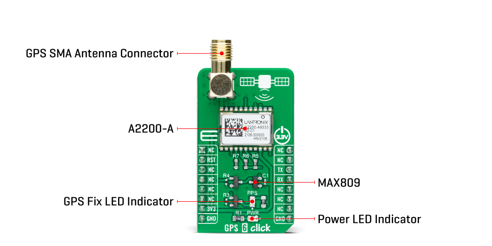
- Based on the A2200-A - high-performance Global Positioning System (GPS) module from Lantronix
- Can be used for a broad spectrum of GPS applications where performance, cost, and time to market are prime considerations
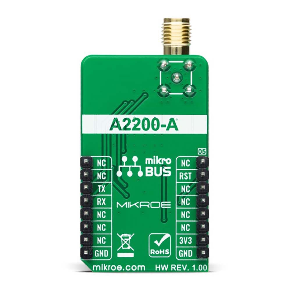
- mikroBUS: UART Interface
Experience precise positioning with the GPS 6 Click Board™
Get ready for high-performance GPS services with the GPS 6 Click Board™, the perfect add-on board for positioning, navigation, and timing. With its compact design, this Click board™ boasts the advanced A2200-A GPS receiver module, which delivers rapid acquisition and tracking through SiRFstar IV technology from Lantronix.
Unbeatable accuracy and power efficiency
Operate with confidence thanks to the GPS 6 Click Board™. Operating at a frequency of 1,575GHz with accuracy from 2 up to 2.5m, this small-form-factor module is the best choice for the lowest power consumption. The removal of jammers guarantees operation even in hostile environments, while its high sensitivity during acquisition or while tracking allows for use in many different backgrounds and under the most challenging operating conditions.
Unleash GPS applications with ease
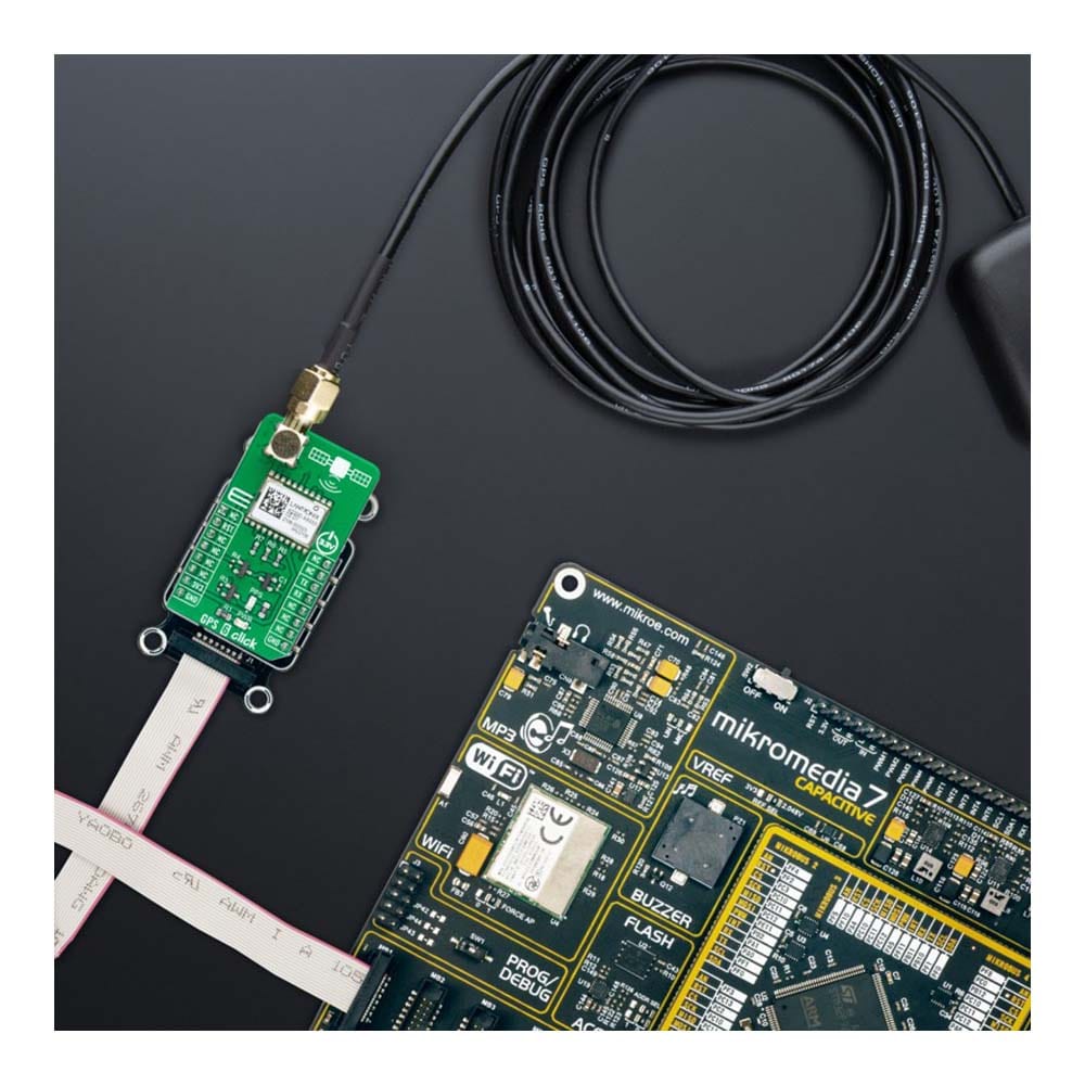
The GPS 6 Click Board™ is a must-have for a broad spectrum of GPS applications where performance, cost, and time to market are prime considerations. Supported by a mikroSDK compliant library, this Click board™ is the perfect solution to simplify software development, making it easy for you to integrate it into your system. This fully tested product comes ready to use on any system equipped with the mikroBUS™ socket.
Experience the ultimate precision with the GPS 6 Click Board™ today!
How Does The GPS 6 Click Board™ Work?
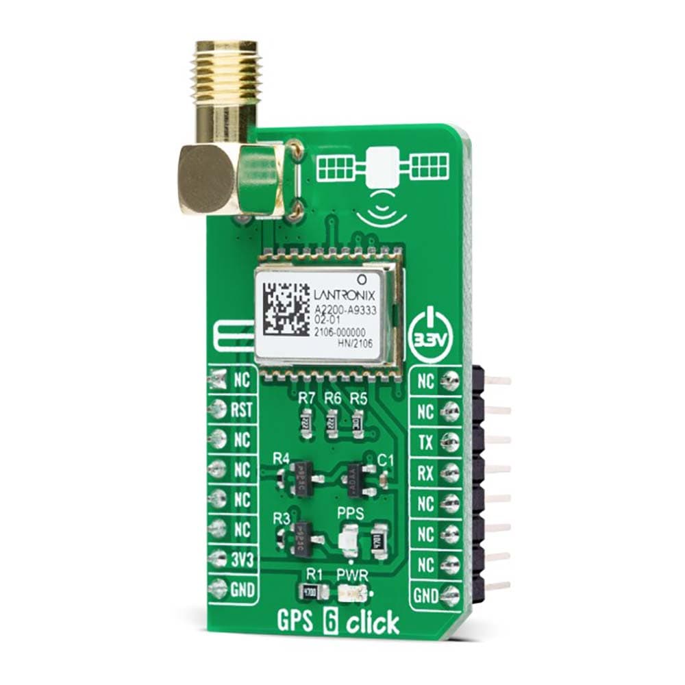
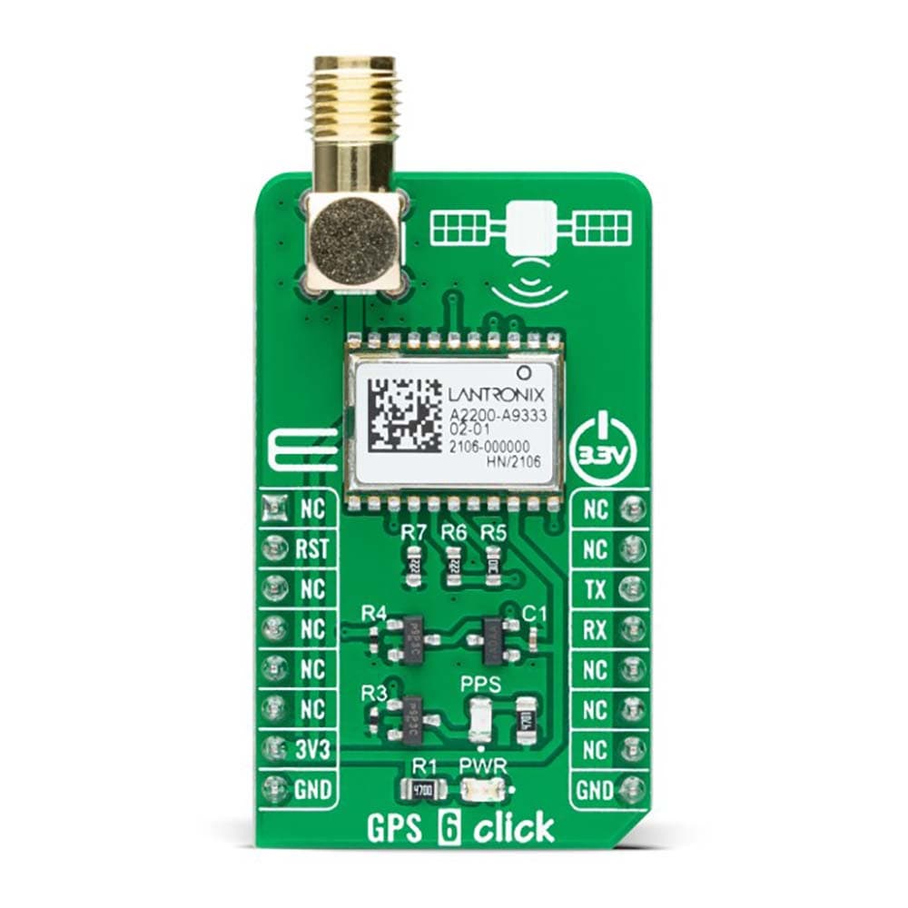
The GPS 6 Click Board™ as its foundation uses the A2200-A, a high-performance Global Positioning System (GPS) module from Lantronix. This GPS module enables fast acquisition and tracking built on the SiRFstar IV technology. It operates with a frequency of 1,575GHz with accuracy from 2 to 2.5m and fully addresses the demand for the lowest power consumption. It is characterized by high sensitivity of -148dBm during acquisition or while tracking (navigation sensitivity of -160dBm and tracking sensitivity of -163dBm) besides removing jammers during acquisition, allowing usage in many different environments and under harsh operating conditions.
The GPS 6 Click Board™ is configured in the Self-Start mode of operation by ON_OFF and WAKEUP pins connected together. The entire power operation will be activated in Self-Start mode once the 3V3 power rail is applied.
The A2200-A communicates with MCU using the UART interface with commonly used UART RX and TX pins as its communication protocol operating at 115200bps by default configuration to transmit and exchange data with the host MCU. It also possesses an active-low reset signal routed on the RST pin of the mikroBUS™ socket that activates a hardware reset of the A2200-A. On this line, the MAX809 is also connected, which performs a single function; it asserts a reset signal whenever the 3V3 supply voltage declines below a preset threshold.
In addition to precise positioning, GPS also allows for accurate timing due to the synchronized atomic clocks in the GPS satellites. While the current date and time are transmitted in NMEA sentences (UTC), a precise and accurate timing signal is provided via the 1PPS pin of the A2200 GPS receiver and indicated via a red LED indicator marked as PPS.
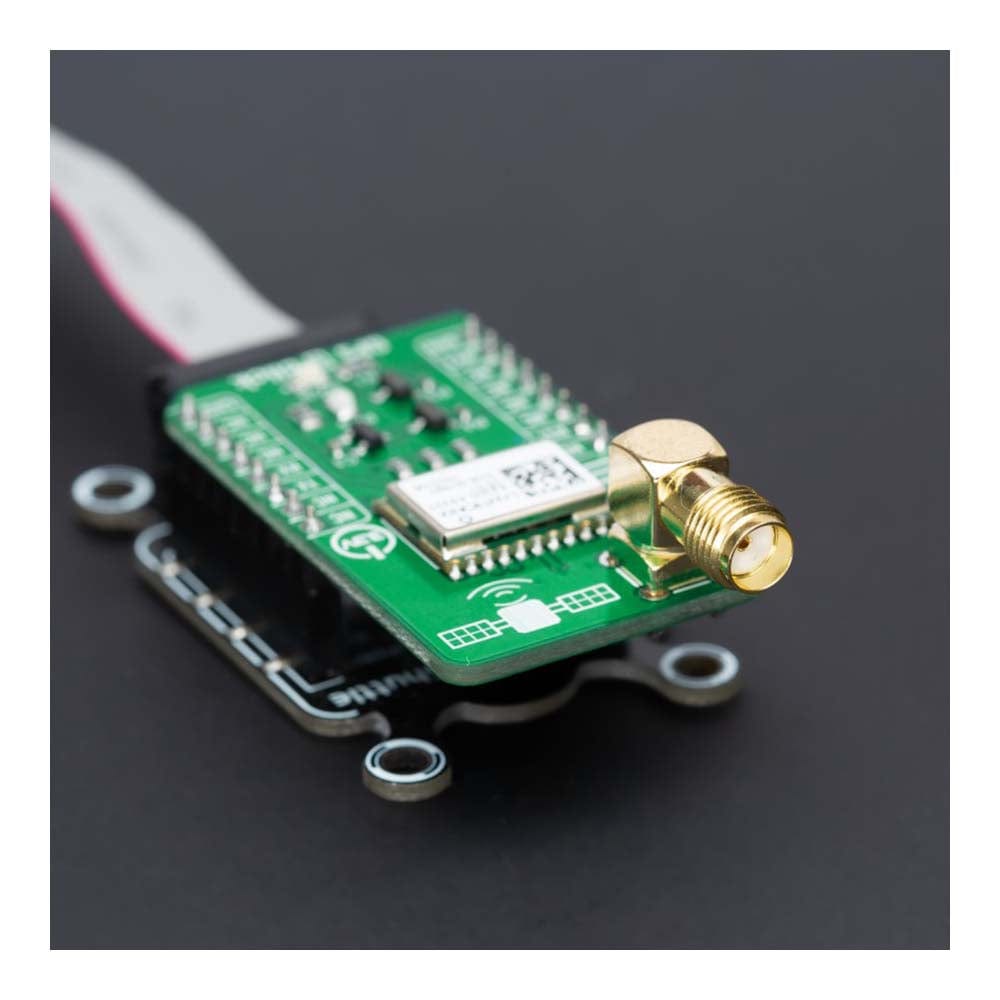
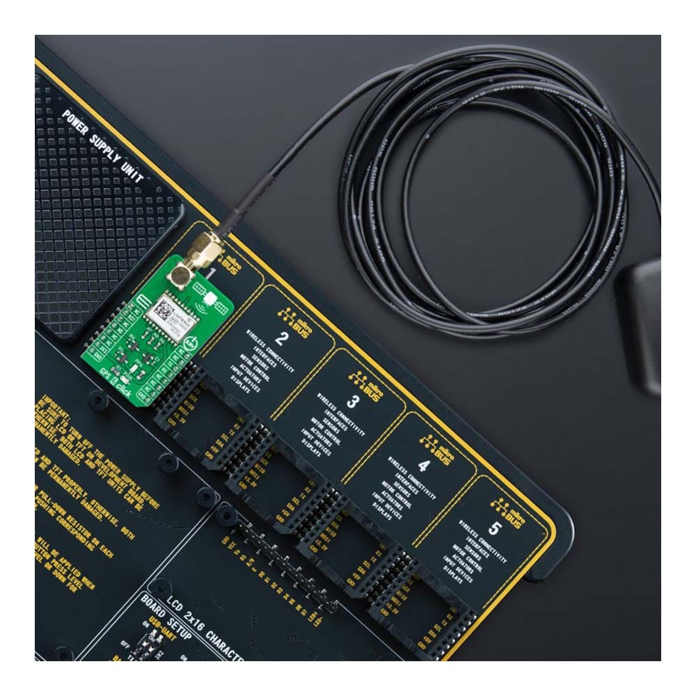
The GPS 6 Click Board™ possesses the SMA antenna connector with an impedance of 50Ω, which can be used to connect the appropriate passive antenna that MikroE has in its offer for improved range and received signal strength.
The GPS 6 Click Board™ can be operated only with a 3.3V logic voltage level. The board must perform appropriate logic voltage level conversion before using MCUs with different logic levels. However, the Click board™ comes equipped with a library containing functions and an example code that can be used, as a reference, for further development.
SPECIFICATIONS
| Type | GPS+GNSS |
| Applications | The GPS 6 Click Board™ can be used for a broad spectrum of GPS applications where performance, cost, and time to market are prime considerations |
| On-board modules | A2200-A - high-performance Global Positioning System (GPS) module from Lantronix |
| Key Features | Complete GPS module, direct passive antenna support, jamming detection and removal, best acquisition and tracking sensitivity, low power consumption, and more |
| Interface | UART |
| Compatibility | mikroBUS |
| Click board size | M (42.9 x 25.4 mm) |
| Input Voltage | 3.3V |
PINOUT DIAGRAM
This table shows how the pinout of the GPS 6 Click Board™ corresponds to the pinout on the mikroBUS™ socket (the latter shown in the two middle columns).
| Notes | Pin | Pin | Notes | ||||
|---|---|---|---|---|---|---|---|
| NC | 1 | AN | PWM | 16 | NC | ||
| Reset | RST | 2 | RST | INT | 15 | NC | |
| NC | 3 | CS | RX | 14 | TX | UART TX | |
| NC | 4 | SCK | TX | 13 | RX | UART RX | |
| NC | 5 | MISO | SCL | 12 | NC | ||
| NC | 6 | MOSI | SDA | 11 | NC | ||
| Power Supply | 3.3V | 7 | 3.3V | 5V | 10 | NC | |
| Ground | GND | 8 | GND | GND | 9 | GND | Ground |
ONBOARD SETTINGS AND INDICATORS
| Label | Name | Default | Description |
|---|---|---|---|
| LD1 | PWR | - | Power LED Indicator |
| LD2 | PPS | - | GPS Fix LED Indicator |
GPS 6 CLICK ELECTRICAL SPECIFICATIONS
| Description | Min | Typ | Max | Unit |
|---|---|---|---|---|
| Supply Voltage | - | 3.3 | - | V |
| Operating Frequency Range | - | 1.575 | - | MHz |
| Position Accuracy | 2 | - | 2.5 | m |
| Tracking Sensitivity | - | -163 | - | dBm |
| Navigation Sensitivity | - | -163 | - | dBm |
| Acquisition Sensitivity | - | -148 | - | dBm |
| Operating Temperature Range | -40 | +25 | +85 | °C |
Software Support
We provide a library for the GPS 6 Click Board™ as well as a demo application (example), developed using MikroElektronika compilers. The demo can run on all the main MikroElektronika development boards.
The package can be downloaded/installed directly from NECTO Studio The package Manager (recommended), downloaded from our LibStock™ or found on MikroE Github account.
Library Description
This library contains API for the GPS 6 Click Board™ driver.
Key functions
-
gps6_enable_deviceThis function enables device by setting the RST pin to LOW logic state. -
gps6_generic_readThis function reads a desired number of data bytes by using UART serial interface. -
gps6_parse_gpggaThis function parses the GPGGA data from the read response buffer.
Example Description
This example demonstrates the use of the GPS 6 Click Board™ by reading and displaying the GPS coordinates.
void application_task ( void )
 {
     gps6_process( &gps6 );
     if ( app_buf_len > ( sizeof ( ( char * ) GPS6_RSP_GPGGA ) + GPS6_GPGGA_ELEMENT_SIZE ) )
     {
         gps6_parser_application( app_buf );
     }
 }
The full application code, and ready to use projects can be installed directly from NECTO Studio The package Manager (recommended), downloaded from our LibStock™ or found on MikroE Github account.
Other MikroE Libraries used in the example:
- MikroSDK.Board
- MikroSDK.Log
- Click.GPS6
Additional Notes and Information
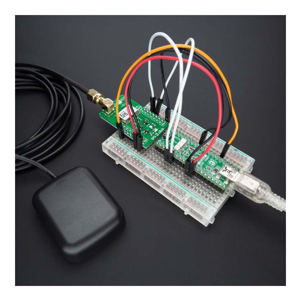
Depending on the development board you are using, you may need USB UART click, USB UART 2 Click or RS232 Click to connect to your PC, for development systems with no UART to USB interface available on the board. UART terminal is available in all MikroElektronika compilers.
MIKROSDK
The GPS 6 Click Board™ is supported with mikroSDK - MikroElektronika Software Development Kit. To ensure proper operation of mikroSDK compliant Click board™ demo applications, mikroSDK should be downloaded from the LibStock and installed for the compiler you are using.
GPS 6 Click Board
Frequently Asked Questions
Have a Question?
Be the first to ask a question about this.