


Mikroelektronika d.o.o.
Current Limit 7 Click Board
Current Limit 7 Click Board
Couldn't load pickup availability
Key Features:
- Integrated protection features, programmable current limiting up to 2.5A, operational and fault indicator, and more
- Based on the MAX14575A - programmable current-limit switch featuring internal current limiting to prevent damage to host devices due to faulty load conditions from Analog Devices
- Can be used for applications in portable equipment and condition monitoring or power supplies, protecting them in short circuits or other overload conditions
- mikroBUS: I2C and GPIO Interfaces
The Current Limit 7 Click Board™ is a compact add-on board representing a current-limiting solution. This board features the MAX14575A, an adjustable current-limit switch from Analog Devices. This Click board™ features internal current limiting to prevent damage to host devices due to faulty load conditions, has a low 32mΩ on-resistance, and operates from a 2.3V to 5.5V input voltage range. Also, the current limit is adjustable from 250mA to 2.5A programmed through AD5272 digital rheostat and set via onboard range switch. This Click board™ is suitable for applications in portable equipment and condition monitoring or power supplies, protecting them in short circuits or other overload conditions.
The Current Limit 7 Click Board™ is supported by a mikroSDK compliant library, which includes functions that simplify software development. This Click board™ comes as a fully tested product, ready to be used on a system equipped with the mikroBUS™ socket.


How Does The Current Limit 7 Click Board™ Work?
The Current Limit 7 Click Board™ is based on the MAX14575A, programmable current-limit switch featuring internal current limiting to prevent damage to host devices due to faulty load conditions from Analog Devices. The MAX14575A offers flexible protection boundaries for systems against input voltage ranging from 2.3V to 5.5V and limits the output load current to a programmed level, up to 2.5A, making this device ideal for charging a large load capacitor as well as for high-current load switching applications. Additional safety features include thermal shutdown protection to prevent overheating and reverse current blocking to prevent current from being driven back into the source.
The current-limit switch provides a safe means for regulating the current delivered to a load circuit. It allows the load current to increase to a programmed limit but no higher. Typically, the current limit is a function of the voltage across an external resistor, and this voltage serves as the reference for an internal current-limiting amplifier. By replacing the resistor with a digital rheostat, you can easily program the current limit as performed on this Click board™. For this purpose, the AD5272 from Analog Devices, communicating with the MCU via 2-Wire I2C interface, is used to set the resistance on the MAX14575A SETI pin, adjusting the current limit for the switch. In this case, two rheostats were used in combination with an onboard switch labelled as RANGE that allows the user to use two possible ranges of current limit: from 0.5A to 2.5A and from 0.25A to 0.5A.
The Current Limit 7 Click Board™ can be enabled or disabled through the EN pin routed to the CS pin of the mikroBUS™ socket; hence, offering a switch operation to turn ON/OFF power delivery to the connected load. It also provides an overcurrent flag (FLG) indication signal routed to the INT pin of the mikroBUS™ socket and an additional reset signal for AD5272 digital rheostat routed to the RST pin of the mikroBUS™ socket.
The Current Limit 7 Click Board™ can operate with both 3.3V and 5V logic voltage levels selected via the VCC SEL jumper. It allows for both 3.3V and 5V capable MCUs to use the communication lines properly. Additionally, there is a possibility for the MAX14575A power supply selection via jumper labelled as PWR SEL to supply the MAX14575A from an external power supply terminal in the range from 2.3V to 5.5V or with VCC voltage levels from mikroBUS™ power rails. However, the Click board™ comes equipped with a library containing easy-to-use functions and an example code that can be used, as a reference, for further development.
SPECIFICATIONS
| Type | Power Switch |
| Applications | The Current Limit 7 Click Board™ be used for applications in portable equipment and condition monitoring or power supplies, protecting them in short circuits or other overload conditions |
| On-board modules | MAX14575A - programmable current-limit switch featuring internal current limiting to prevent damage to host devices due to faulty load conditions from Analog Devices |
| Key Features | Integrated protection features, programmable current limiting up to 2.5A, operational and fault indicator, and more |
| Interface | GPIO,I2C |
| Compatibility | mikroBUS |
| Click board size | M (42.9 x 25.4 mm) |
| Input Voltage | 3.3V or 5V,External |
PINOUT DIAGRAM
This table shows how the pinout of the Current Limit 7 Click Board™ corresponds to the pinout on the mikroBUS™ socket (the latter shown in the two middle columns).
| Notes | Pin | Pin | Notes | ||||
|---|---|---|---|---|---|---|---|
| NC | 1 | AN | PWM | 16 | NC | ||
| Reset | RST | 2 | RST | INT | 15 | FLG | Overcurrent Indicator |
| Enable | EN | 3 | CS | RX | 14 | NC | |
| NC | 4 | SCK | TX | 13 | NC | ||
| NC | 5 | MISO | SCL | 12 | SCL | I2C Clock | |
| NC | 6 | MOSI | SDA | 11 | SDA | I2C Data | |
| Power Supply | 3.3V | 7 | 3.3V | 5V | 10 | 5V | Power Supply |
| Ground | GND | 8 | GND | GND | 9 | GND | Ground |
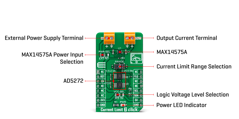
ONBOARD SETTINGS AND INDICATORS
| Label | Name | Default | Description |
|---|---|---|---|
| LD1 | PWR | - | Power LED Indicator |
| JP1 | VCC SEL | Left | Logic Level Voltage Selection 3V3/5V: Left position 3V3, Right position 5V |
| JP2 | PWR SEL | Left | MAX14575A Power Input Selection EXT/INT: Left position EXT, Right position INT |
| SW1 | RANGE | - | Current Limit Range Selection Switch |
CURRENT LIMIT 7 CLICK ELECTRICAL SPECIFICATIONS
| Description | Min | Typ | Max | Unit |
|---|---|---|---|---|
| Supply Voltage VCC | 3 | - | 5 | V |
| External Supply Voltage IN | 2.3 | - | 5.5 | V |
| Current Limit Range OUT | 0.25 | - | 2.5 | A |
| Operating Temperature Range | -40 | +25 | +85 | °C |
Software Support
We provide a library for the Current Limit 7 Click Board™ as well as a demo application (example), developed using MikroElektronika compilers. The demo can run on all the main MikroElektronika development boards.
The package can be downloaded/installed directly from NECTO Studio The package Manager (recommended), downloaded from our LibStock™ or found on MikroE Github account.
Library Description
This library contains API for the Current Limit 7 Click Board™ driver.
Key functions
-
currentlimit7_set_current_limitCurrent Limit 7 set current limit function. -
currentlimit7_set_resistanceCurrent Limit 7 set resistance function. -
currentlimit7_get_faultCurrent Limit 7 get fault function.
Example Description
This library contains API for the Current Limit 7 Click Board™ driver. This driver provides the functions to set the current limiting conditions in order to provide the threshold of the fault conditions.
void application_task ( void )
{
static char index;
if ( CURRENTLIMIT7_ERROR != log_read( &logger, &index, 1 ) )
{
#ifdef CURRENTLIMIT_MODE_250_mA_500_mA
if ( ( index >= '0' ) && ( index <= '3' ) )
{
currentlimit7_set_current_limit ( ¤tlimit7, CURRENTLIMIT7_OP_MODE_250_mA_500_mA, limit_value_op[ index - 38 ] );
log_printf( &logger, " >>> Selected mode %d rn", index - 48 );
log_printf( &logger, "- - - - - - - - - - - - - -rn" );
log_printf( &logger, " Current limit is %d mA rn", limit_value_op[ index - 38 ] );
log_printf( &logger, "---------------------------rn" );
Delay_ms( 100 );
}
#else
if ( ( index >= '0' ) && ( index <= '9' ) )
{
currentlimit7_set_current_limit ( ¤tlimit7, CURRENTLIMIT7_OP_MODE_500_mA_2500_mA, limit_value_op[ index - 48 ] );
log_printf( &logger, " >>> Selected mode %d rn", index - 48 );
log_printf( &logger, "- - - - - - - - - - - - - -rn" );
log_printf( &logger, " Current limit is %d mA rn", limit_value_op[ index - 48 ] );
log_printf( &logger, "---------------------------rn" );
Delay_ms( 100 );
}
#endif
else
{
log_printf( &logger, " Data not in range! rn" );
log_printf( &logger, "---------------------------rn" );
display_selection( );
Delay_ms( 100 );
}
}
}
The full application code, and ready to use projects can be installed directly from NECTO Studio The package Manager (recommended), downloaded from our LibStock™ or found on MikroE Github account.
Other MikroE Libraries used in the example:
- MikroSDK.Board
- MikroSDK.Log
- Click.CurrentLimit7
Additional Notes and Information
Depending on the development board you are using, you may need USB UART click, USB UART 2 Click or RS232 Click to connect to your PC, for development systems with no UART to USB interface available on the board. UART terminal is available in all MikroElektronika compilers.
MIKROSDK
The Current Limit 7 Click Board™ is supported with mikroSDK - MikroElektronika Software Development Kit. To ensure proper operation of mikroSDK compliant Click board™ demo applications, mikroSDK should be downloaded from the LibStock and installed for the compiler you are using.
Current Limit 7 Click Board
Frequently Asked Questions
Have a Question?
Be the first to ask a question about this.