

Mikroelektronika d.o.o.
Hall Current 4 Click Board™
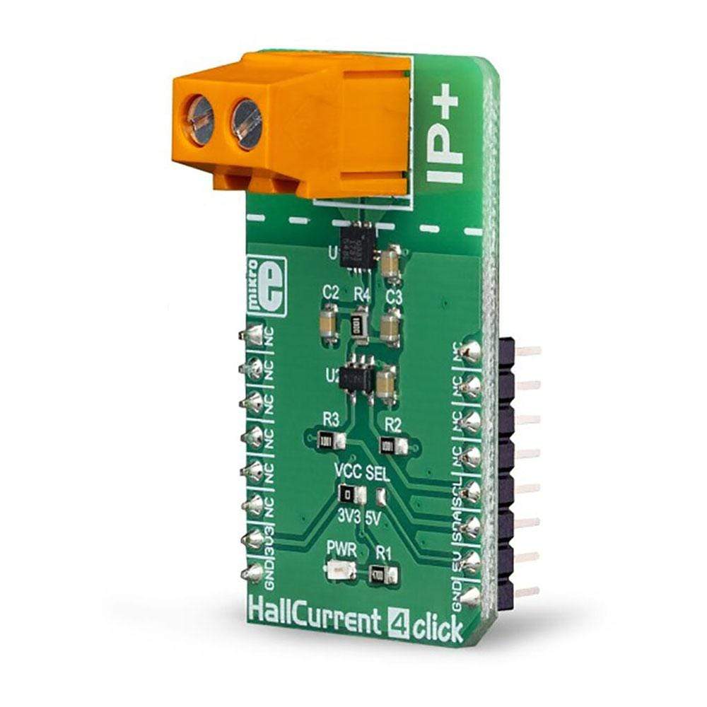
Hall Current 4 Click Board™
SKU: MIKROE-3308
Couldn't load pickup availability


Overview
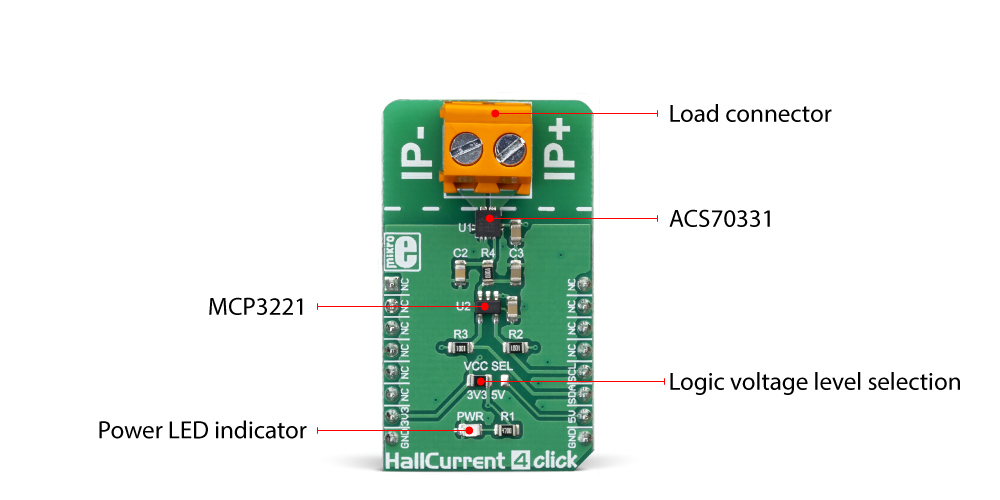
The Hall Current 4 Click Board™ is designed to measure relatively high current by using the integrated ACS70331 sensor. The current sensor is based on the GMR elements for current measurement. The Hall Current 4 Click Board™ can be used for current measurement in the applications designed to follow a current, such as the applications for monitoring the current in battery chargers, or for the various kinds of system power supplies.
Downloads
 DO NOT TOUCH THE BOARD WHILE THE EXTERNAL POWER SUPPLY IS ON!
Note: Voltage higher than 50V can be hazardous! The click is to be used by trained personnel only and attention when applying high voltage is strongly adviced.
Due to the fact that the sensor provides a solely analog voltage at its output which is linearly commensurate to the current through the load connected to the output terminal, the Hall Current 4 Click Board™ also has the integrated analog-digital converter which serves to transform the output voltage from the ACS70331 to digital value. The digital value is possible to read from the I2C interface.
How Does The Hall Current 4 Click Board™ Work?
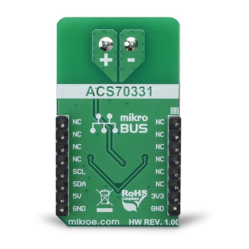
The Hall Current 4 Click Board™ uses the ACS70331 current sensor produced by Allegro, and the 12-bit ADC marked MCP3221, produced by Microchip. The ACS70331 uses GMR elements to indirectly measure the current flowing through the primary conductor of the IC, by sensing the field produced by this current. This IC utilizes the fact that the field generated by the current passing through the primary conductor affects the voltage across the GMR sensor. The GMR sensor voltage cahnges even with a very low field strength, which makes the ACS70331 very suitable for accurate measurements of lower currents. However, the saturation happens quite soon after, making it unsuitable for higher currents. The ACS70331 has the sensitivity of 200 mV/A and can measure the current in the range range from -5A to +5A
Considering that the operative range of the ACS70331 is approximately 1 MHz, the variations of the output voltage with the load current are quite fast with no latency. The output voltage from the ACS70331 is fed to the input of the analog-digital converter (ADC) which which allows reading the conversion data via the I2C interface. The ACS70331 has a small primary conductor resistance of 1.1 mΩ, resulting in low power dissipation and consequently low temperature rise due to current flow through the sensor.
The sensor has no physical contact with the output pins on the chip as it operates exclusively by the principle of the filed generated by the current which runs through the input pins (primary conductor). The load voltage at the input pins is isolated from the rest of the chip. However, it is not safe to use at the voltages higher than 100V.
SPECIFICATIONS
| Type | Current sensor |
| Applications | The Hall Current 4 Click Board™ is perfect for various applications designed for current sensing, e.g. monitoring the current in battery chargers, or for the various kinds of system power supplies, etc. |
| On-board modules | IC ACS70331, high sensitivity GMR-based current sensor IC, by Allegro |
| Key Features | Very low serial resistance, measurement of relatively high voltage values – up to 5A independent from the polarization, great accuracy thanks to the GSR current sensor, big range of power supply voltages to which the load can be amounted, etc. |
| Interface | I2C |
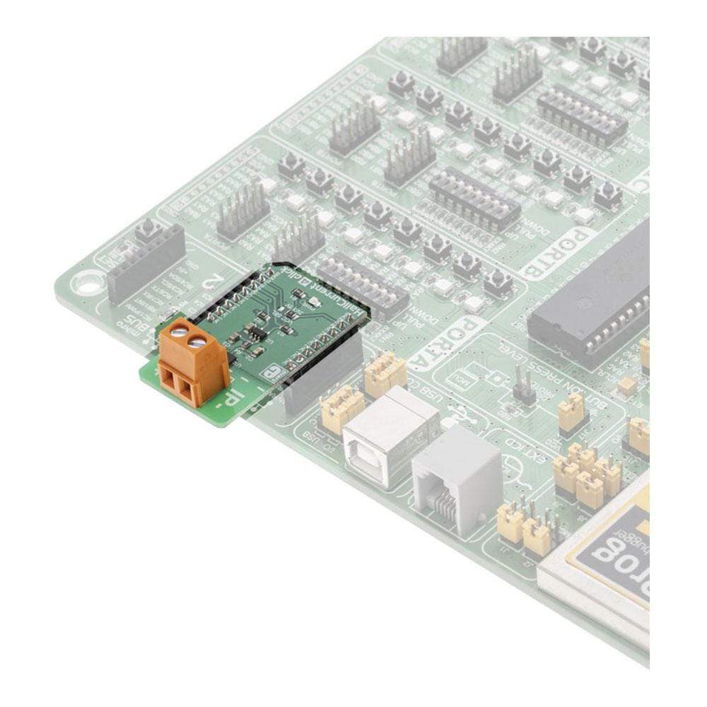
| Compatibility | mikroBUS |
| Click board size | M (42.9 x 25.4 mm) |
| Input Voltage | 3.3V or 5V |
PINOUT DIAGRAM
This table shows how the pinout on the Hall Current 4 Click Board™ corresponds to the pinout on the mikroBUS™ socket (the latter shown in the two middle columns).
| Notes | Pin | Pin | Notes | ||||
|---|---|---|---|---|---|---|---|
| NC | 1 | AN | PWM | 16 | NC | ||
| NC | 2 | RST | INT | 15 | NC | ||
| NC | 3 | CS | RX | 14 | NC | ||
| NC | 4 | SCK | TX | 13 | NC | ||
| NC | 5 | MISO | SCL | 12 | SCL | I2C Clock | |
| NC | 6 | MOSI | SDA | 11 | SDA | I2C Data | |
| Power supply | 3V3 | 7 | 3.3V | 5V | 10 | +5V | Power Supply |
| Ground | GND | 8 | GND | GND | 9 | GND | Ground |
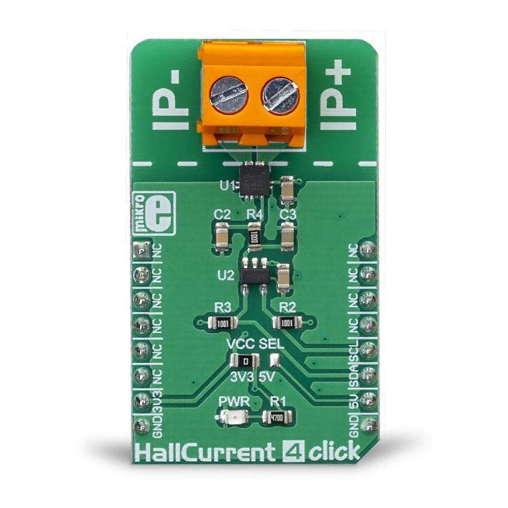
ONBOARD SETTINGS AND INDICATORS
| Label | Name | Default | Description |
|---|---|---|---|
| VCC SEL | VCC SEL | Left | Logic voltage level selection: left position 3.3V, right position 5V |
| PWR | PWR | - | Power LED indicator |
HALL CURRENT 4 CLICK ELECTRICAL SPECIFICATIONS
| Description | Min | Typ | Max | Unit |
|---|---|---|---|---|
| Current range | -5 | - | +5 | A |
| Allowed voltage across the input terminal | 0 | - | 100 | V |
| General Information | |
|---|---|
Part Number (SKU) |
MIKROE-3308
|
Manufacturer |
|
| Physical and Mechanical | |
Weight |
0.021 kg
|
| Other | |
EAN |
8606018714216
|
Frequently Asked Questions
Have a Question?
Be the first to ask a question about this.