How To Use Tag-Connect Cables With The ST-Link V3 Set Debugger
ST-Link V3 SET Cable Selection & Installation

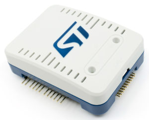
STLINK-V3 is modular in that it has a “Main module” Hardware board (MB1441) which, ST documentation suggests, offers higher performance using a 14-pin 0.05″ connector, but also comes with an optional mezzanine board (MB1440) which offers more connections (presumably with potentially lower performance) including: Traditional 20-pin 0.1″ ARM connector (JTAG20), a 4-pin SWIM header, a 6-pin SWD header, and other pin headers offering access to VCP, SPI, UART, I2C, CAN and GPIO connections.
Tag-Connect has a comprehensive set of solutions for use with ST-LINK/V3.
NOTE: ST-LINK/V2 could supply the target with 3.3V via pin 19 of the 20-pin connector. STLINK-V3 can only supply the target with 5V power AND the 5V power appears to be connected to VCC of the target by default! You’ll may need to disconnect a jumper on one of the STLINK-V3SET boards to defeat this.
1. Full traditional JTAG using our TC2050-ARM2010 adapter TC2050-IDC 10-pin Plug-of-Nails(tm) cables. Compatible with all ARM processors. This solution offers a more robust / longer lasting ribbon cable but has the disadvantage of requiring the cumbersome mezzanine board.
2. SWD (Serial Wire Debug) interface using ARM20 connector with smaller footprint solution for Cortex processors using the ARM20-CTX and the TC2030-IDC cable.
Both solutions are similar in that they use a 20-pin to Tag-Connect adapter. However, the Full Traditional JTAG also allows you to optionally power the target from the debugger and provides access to all of the signals provided by the traditional 20-pin ARM 0.1″ connection whereas the SWD (Serial Wire Debug)solution only supplies access to the signals used by the SWD protocol.
3. SWD using the Cortex STDC14 connector and TC2030-CTX-STDC14 or TC2030-CTX-NL-STDC14 cable providing a 14-pin 0.05″ Cable that plugs to the bottom of the STLINK-V3 and has a 6-pin TC2030 (-NL) connector on the other end. This cable provides signals for SWD protocol. A disadvantage is the very fine pitch of the ribbon cable which is less robust and might not last as long as Solution 2 above. However, you don’t need the add-on board with these cables.
4. SWIM solution for STM8.
5. JTAG, SWD & UART using Cortex STDC14 to 14 Pin target board connector. TC2070-IDC-050 or TC2070-IDC-NL-050 14-pin cables providing a TC2070 14-pin connection to the PCB. The advantage to these cables is they provide all 14-pins including the UART. A disadvantage is the very fine ribbon cable which may not last as long as the other solutions.
Full Traditional JTAG using TC2050 and TC2050-ARM2010 adapter
Both solutions for the ST-LINK/V2 are similar in that it requires an adapter and a cable, so it is up to you which one you will go for depending on your PCB needs. Here is the first solution:
Connect the TC2050-ARM2010 to the ST-LINK/V2 and connect the TC2050-IDC cable to the adapter.
Both “legged” and “no-leg” cables come in the standard 6″ length.The TC2050-IDC-NL will require the TC2050-CLIP if you want a hands-free solution while debugging.
