DDC, EDID and Display Control Channels
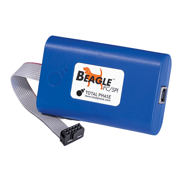
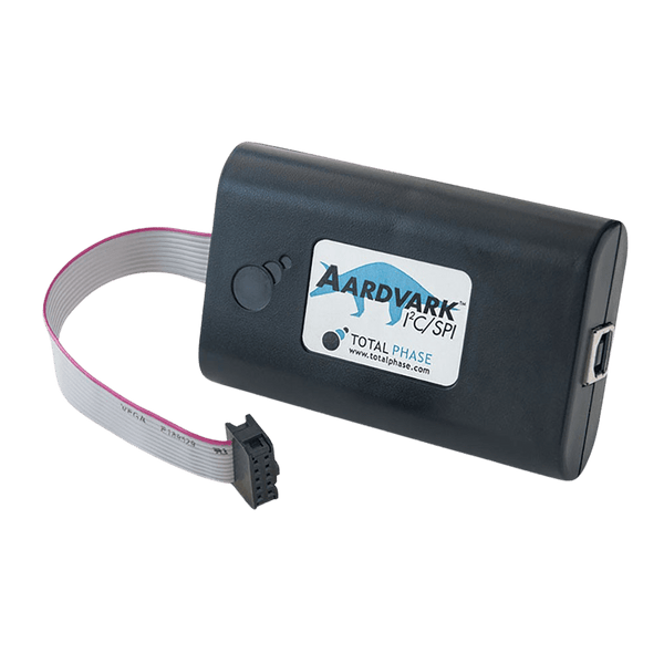
DDC (Display Data Channel) is the I2C bus inside every VGA, DVI and HDMI cable. A video source uses it to read the display's EDID (Extended Display Identification Data), which lists the resolutions, timings and audio formats the display supports. HDMI adds CEC for remote control, and DisplayPort replaces DDC with its AUX channel. Because DDC is I2C, an I2C protocol analyser such as the Beagle I2C/SPI can watch it through a DDC breakout cable, and a host adapter such as the Aardvark can read or rewrite an EDID.
Where the DDC Lines Are
| Connector | DDC SCL | DDC SDA | +5 V | Hot Plug Detect |
|---|---|---|---|---|
| VGA (DE-15) | Pin 15 | Pin 12 | Pin 9 | Not defined |
| DVI | Pin 6 | Pin 7 | Pin 14 | Pin 16 |
| HDMI Type A | Pin 15 | Pin 16 | Pin 18 | Pin 19 |
The source supplies +5 V so the display's EDID memory can be read even with the display switched off. On DVI and HDMI the display answers by raising hot plug detect (HPD), which tells the source a display is connected and the EDID is ready. HDMI CEC is on pin 13 of the HDMI connector.
How an EDID Read Works
- Hot plug: the source sees HPD go high and waits briefly for the display to settle.
- Segment pointer: for EDIDs over 256 bytes, the source writes a segment number to address 0x30 (E-DDC), selecting which pair of 128-byte blocks to read next. Older sources skip this and read only the first 256 bytes.
- Offset and read: the source writes a byte offset to address 0x50, sends a repeated Start and reads 128 bytes or more.
- Check: the source checks the fixed header (00 FF FF FF FF FF FF 00) and the checksum of each block, then reads the extension count in byte 126 and fetches the extension blocks.
- HDMI extras: HDCP authentication uses the same lines at address 0x3A, and HDMI 2.0 and later sources use SCDC at address 0x54 to set up scrambling for high pixel clocks.
What Is in an EDID
| Bytes | Content |
|---|---|
| 0 to 7 | Fixed header |
| 8 to 17 | Manufacturer ID, product code, serial number, week and year of manufacture |
| 18 to 19 | EDID version and revision, normally 1.4 (1.3 on older displays) |
| 20 to 24 | Input type and bit depth, screen size, gamma, supported features |
| 25 to 34 | Colour characteristics |
| 35 to 53 | Established and standard timings |
| 54 to 125 | Four 18-byte descriptors: the preferred detailed timing first, then display name, range limits or more timings |
| 126 | Number of extension blocks |
| 127 | Checksum: all 128 bytes add up to 0, modulo 256 |
The usual extension is a CTA-861 block, which carries the HDMI vendor-specific data (including the CEC physical address), audio formats, extra video modes and HDR metadata. DisplayID blocks appear on newer displays.
HDMI CEC
Consumer Electronics Control lets HDMI devices control each other: one remote powering on a TV, soundbar and player together. It is a single-wire, open-drain bus on HDMI pin 13, shared by every device in the system, with a pull-up to 3.3 V. Bits are about 2.4 ms long, so the bus runs at roughly 400 bit/s, and each frame starts with a 4.5 ms start bit. Each device takes a logical address (0 for the TV, 4 for the first playback device, 15 for broadcast), and its physical address comes from the EDID of the device it is plugged into, normally the TV, or an AV receiver or switch in between. A CEC fault shows up as one device ignoring the others, and a logic analyser with a CEC decoder or an oscilloscope on pin 13 shows who is transmitting and who acknowledges.
DisplayPort AUX Channel
Native DisplayPort has no DDC lines. (A dual-mode DP++ source driving a passive HDMI or DVI adapter switches its AUX pins to DDC instead.) Its AUX channel is a half-duplex, AC-coupled differential pair running Manchester-coded transactions at about 1 Mbit/s. The source uses it for link training, to read and write the display's DPCD registers (capabilities and link status), for HDCP, and to read the EDID by tunnelling I2C transactions over AUX ("I2C-over-AUX"). An I2C analyser cannot see AUX traffic; you need a logic analyser with a DP AUX decoder and a differential probe or suitable front end.
Common DDC and EDID Faults and How to Find Them
| Symptom | Likely Cause | What to Check |
|---|---|---|
| Wrong or limited resolution offered | EDID read failed, so the source fell back to safe modes | Capture the DDC traffic at hot plug: look for a NACK at 0x50 or a checksum error |
| Works on one PC, not another | One source reads only 256 bytes and misses extension blocks, or ignores the segment pointer | Compare the two captures: does the failing source write to 0x30? |
| No picture through a switch or extender | The device in the middle does not pass HPD or presents its own EDID | Read the EDID seen at the source end with a host adapter and compare |
| Audio missing over HDMI | CTA-861 extension block missing or has no audio descriptors | Decode the extension block's audio data block |
| One HDMI device ignores the remote | CEC logical or physical address conflict, or CEC line pulled down | Decode CEC traffic on pin 13 and look for unacknowledged frames |
| DisplayPort link drops after training | AUX transactions failing or link training retries | Decode AUX for repeated DPCD writes to the training registers |
Tools for Analysing DDC, EDID, CEC and AUX
Watch tools capture traffic between a real source and display. Drive tools read, write or emulate an EDID from a PC.
Protocol Analyser and Host Adapter With DDC Breakout Cables
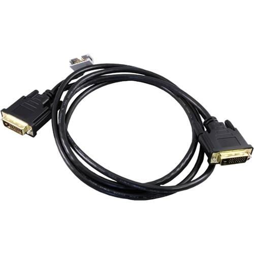
Total Phase makes DDC breakout cables for DVI and VGA. For HDMI, use the DVI cable with a DVI-to-HDMI adapter at each end: DDC, +5 V and hot plug detect pass straight through.
| Product | Role | Capability | Price ex VAT |
|---|---|---|---|
| Total Phase Beagle I2C/SPI (TP320121) | Watch | Monitors the DDC I2C traffic between source and display, including EDID, HDCP and SCDC reads, with timestamps | €500,95 |
| Total Phase Aardvark (TP240141) | Drive | Reads a display's EDID, or writes a new one to a rewritable EDID EEPROM, from Control Center Serial or the software API | €419,95 |
| TP240810 DVI DDC Breakout Cable | 2 m single-link DVI-D cable with a 10-pin DDC header that connects to the Beagle or Aardvark | €125,95 | |
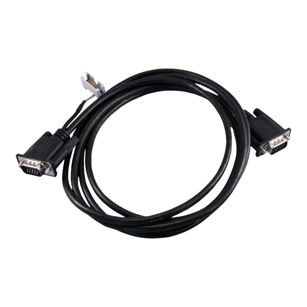
| TP240910 VGA DDC Breakout Cable | 2 m VGA cable with the same 10-pin DDC header | €125,95 |
Logic Analysers With DDC, CEC and AUX Decoding
| Product | Role | Capability | Price ex VAT |
|---|---|---|---|
| Saleae Logic 8 | Watch | 8 channels; I2C decoding for DDC and an HDMI CEC decoder in the Logic 2 software | €506,95 |
| ZeroPlus LAP-C Pro Series | Watch | Logic analyser; ZeroPlus lists DDC EDID, HDMI CEC and DisplayPort AUX decoders (ask us to confirm availability for your LAP-C Pro model); DP AUX needs a differential probe or front end | €1.157,95 |
| Acute TravelLogic 34-Channel | Watch | Logic analyser running Acute's decoder library, which includes DDC (EDID) and DisplayPort AUX; DP AUX also needs Acute's optional DP AUX adapter | €1.453,95 |
For the I2C layer underneath DDC, see our I2C protocol guide. Need to emulate a display for production test? Tell us the connector and EDID you need and we will suggest a set-up.
Frequently Asked Questions
Is DDC the Same as I2C?
Electrically, yes: DDC2B is an I2C bus at up to 100 kHz on 5 V. It adds rules about which addresses are used (0x50 for EDID, 0x30 for the segment pointer) and when the source may read. Any I2C analyser can capture it if you can reach the lines.
How Do I Read a Monitor's EDID?
Connect a host adapter such as the Aardvark to the DDC lines through a breakout cable, supply the +5 V the monitor expects, then read 128 bytes from address 0x50, starting at offset 0. Read byte 126 to see how many extension blocks follow.
Can I Change a Display's EDID?
Only if the EDID is held in a writable EEPROM and write protect is off, which is uncommon on finished monitors but common on development boards, KVMs and video capture devices. Back up the original first, and keep the checksum correct or sources will reject the block.
Why Does My Capture Show NACKs at 0x50?
The display's EDID did not answer. Check that +5 V reaches the display, that HPD is high, and that the display or an extender in between is not holding the bus. A NACK is also normal if the source probes before the display is ready.
Do I Need a Different Tool for DisplayPort?
Yes. Native DisplayPort has no DDC lines: the EDID travels over the differential AUX channel. (Only a DP++ port driving a passive HDMI or DVI adapter falls back to DDC.) You need a logic analyser with a DisplayPort AUX decoder and a way to probe the AUX pair, not an I2C analyser.
Where to Start with DDC, EDID, HDMI CEC and DisplayPort AUX
More Protocols
By John Legg CEng, Director, Debug Store. Updated 12 November 2026.
