Mikroelektronika d.o.o.
Color Click Board
Color Click Board
Couldn't load pickup availability
Overview
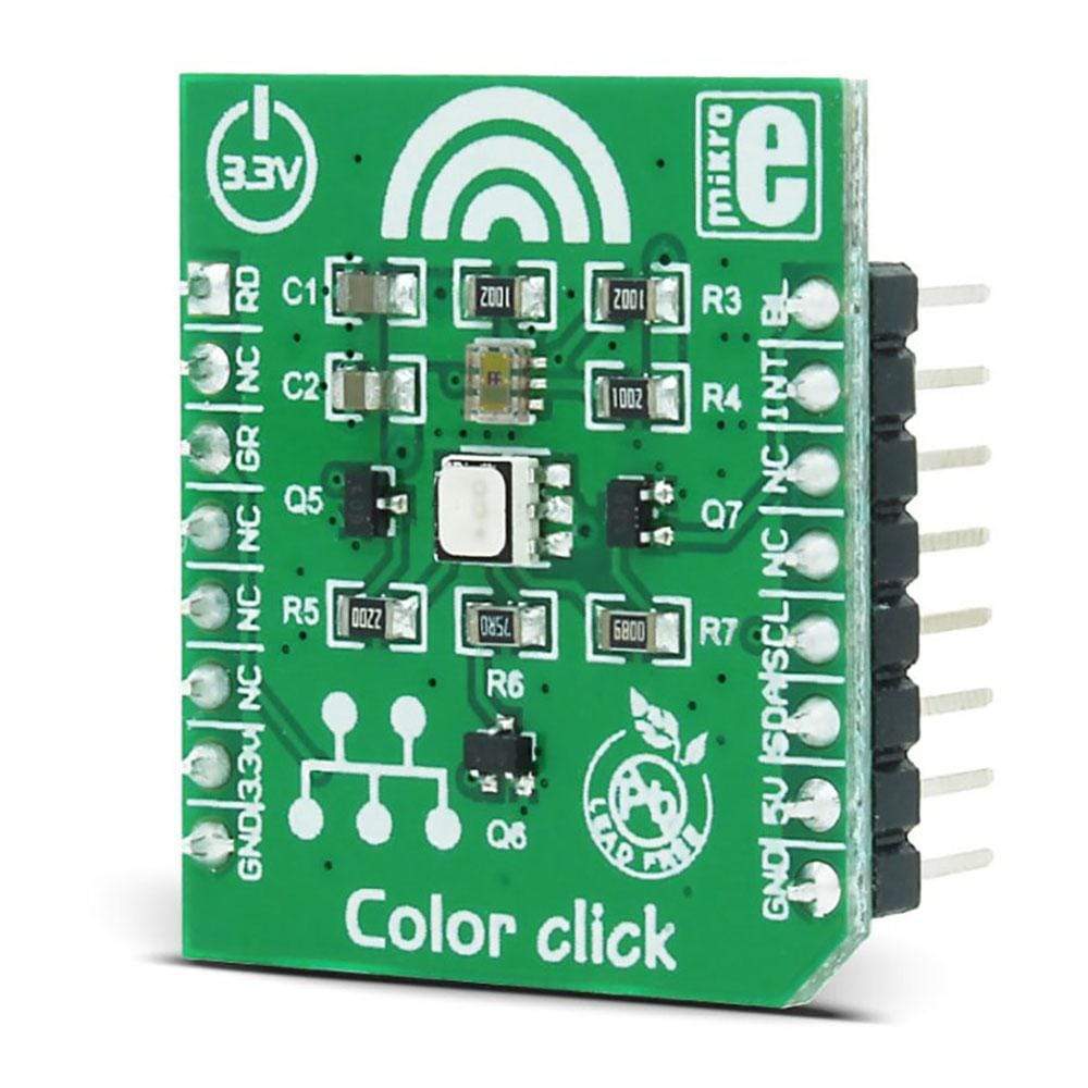
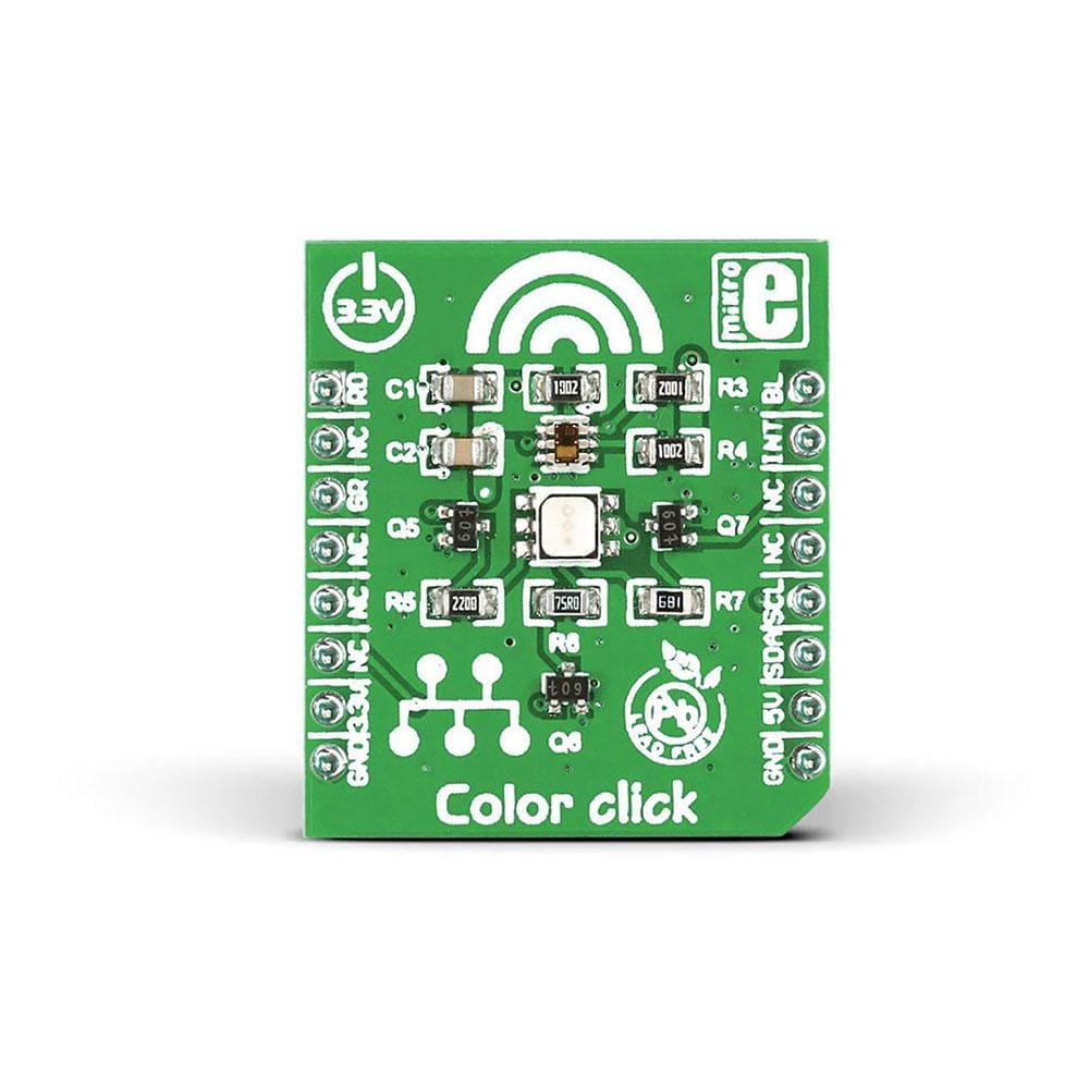
Add colour sensing functionality to your device with the MikroE Color Click Board™. This compact accessory board employs TCS3471 colour light-to-digital converter sensor, three NPN resistor-equipped transistors, as well an RGB LED diode. With a resolution of up to 16 bits, the TCS3471 colour light sensor provides red, green, blue, and clear light sensing (RGBC) that detects light intensity under a variety of lighting conditions and through a variety of attenuation materials. The Color Click Board™ uses the MikroBUS I2C lines (SDA and SCK) to communicate with the target microcontroller and uses 3 digital output lines to drive RGB LED. Featuring a programmable interrupt function, it reduces microprocessor interrupt overhead. The board is designed to use a 3.3V power supply only.
In the absence of any light source, RGB LED provides light for the illumination of objects. The Color Click Board™ is an ideal choice for RGB LED backlight control, a light colour temperature monitor, industrial process control, medical diagnostic equipment, healthcare/medical, and many more.
The sensor uses the industry standard I2C interface to exchange data with the host MCU. The high brightness RGB LED can be simply driven by MCU pins since it has three driving transistors onboard which provide enough current for the segments. The Click board™ is an ideal solution for various colored light sensing applications, or for simple object recognition. It can be used for the RGB LED color correction, backlight adjustment, in robotics - for the object color recognition, light color temperature sensing, and similar applications that require accurate and flexible color sensing.
How Does The Color Click Board™ Work?
The Color Click Board™ has two active components used to sense color: it is equipped with the popular TCS3471 integrated color light-to-digital converter by AMS-TAOS, and the LRTB GFTG, a high brightness RGB LED, from Osram Opto-semiconductors. The TCS3471 color sensor features a 4x4 array of photo-diodes, which allow detection of each light component: red, green, and blue (R, G, B). Additionally, it can sense the clear light component, too. The sensor IC has a programmable gain control (for all segments simultaneously), applying gain ratios of 1, 4, 16, and 60. This allows the optimal range of the A/D converters (ADC) to be used.
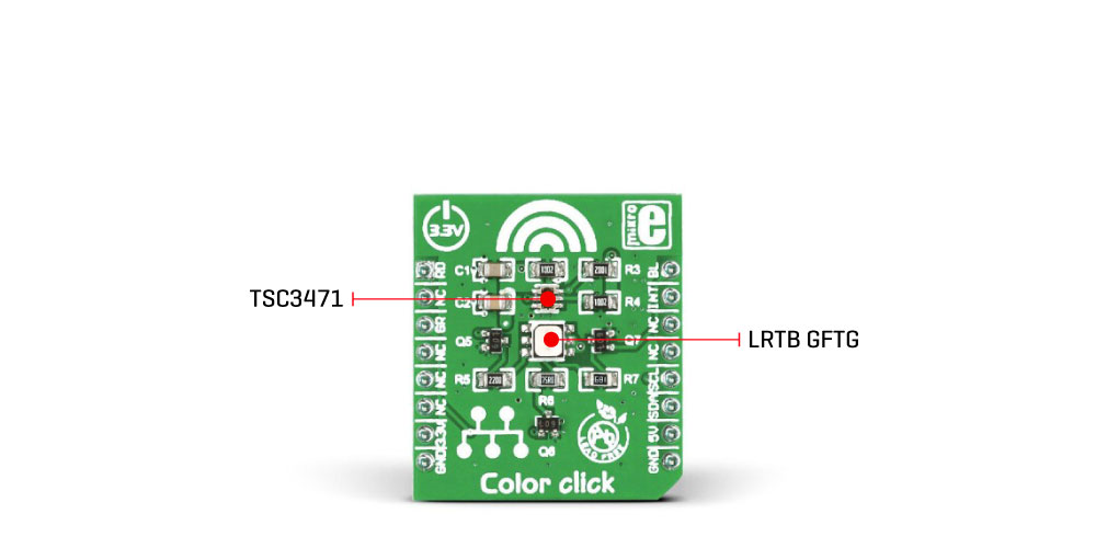
The sensor has an integrating 16-bit ADC section for each channel, performing signal integration, which affects both the sensitivity and the acquisition time. When the conversion is done, the results are stored on the output registers in 16-bit format. The data transfer is double buffered, preventing reading errors, while the conversion is in progress. The sensor does not have any IR filter, thus it has to be placed under the IR blocking glass if sensing ambient light. However, it is ideally suited for the RGB lighting applications, since the LEDs emit light in reasonably narrow spectrum bands, with no IR component. The sensor can achieve dynamic range up to 1,000,000:1 in such scenario.
The interrupt pin is an open drain type, routed to the mikroBUS™ INT pin. It is used to alert the MCU when a certain condition is reached: there are two 16-bit registers which contain upper and lower thresholds for the color intensity reading. Furthermore, a persistence filter allows triggering interrupts only when enough out-of-range events are accumulated. The number of out-of-range occurrences before the interrupt is triggered are configured via the appropriate register.
The TCS3471 sensor is driven by the state machine. It controls the operation of the sensor, via the state bits found in the ENABLE register. This register contains bits that control the ADC operation, power-on operation, enable interrupt engine, enable wait timers, and so on. The full list of registers and the in-depth explanation is provided in the TCS3471 datasheet. However, libraries provided with the Click board™ offer easy to use functions, which accelerate the prototyping and cut the time to market.
The Osram RGB LED is controlled directly, via the GPIO pins of the host controller. The bases of three transistors are routed to AN, CS and PWM pins of the mikroBUS™. Logic HIGH level on the base will bias the transistor so it allows current flowing through the RGB LED segments. The current through the LED is limited by a series resistor, so it won't damage both LED and the transistors. This LED provides a limited amount of controlled light, which can be used to illuminate the measured object in low light situations. Instead of HIGH or LOW logic levels, it is possible to bring the PWM signal to these pins, which will allow brightness control of the R,G, and B segments of the LRTB GFTG.
SPECIFICATIONS
| Type | Color Sensing,Optical |
| Applications | The Color Click Board™ is an ideal solution for RGB LED color correction, backlight adjustment, in robotics - for the object color recognition, light color temperature sensing, and similar applications that require accurate and flexible color sensing |
| On-board modules | TCS3471 integrated color light-to-digital converter, by ams-TAOS; LRTB GFTG RGB LED from Osram |
| Key Features | High dynamic range, red, green, blue, and clear light detection, onboard RGB led for low light situations, fast I2C communication, buffered writes for increased data reliability, programmable interrupt engine, and more |
| Interface | GPIO,I2C |
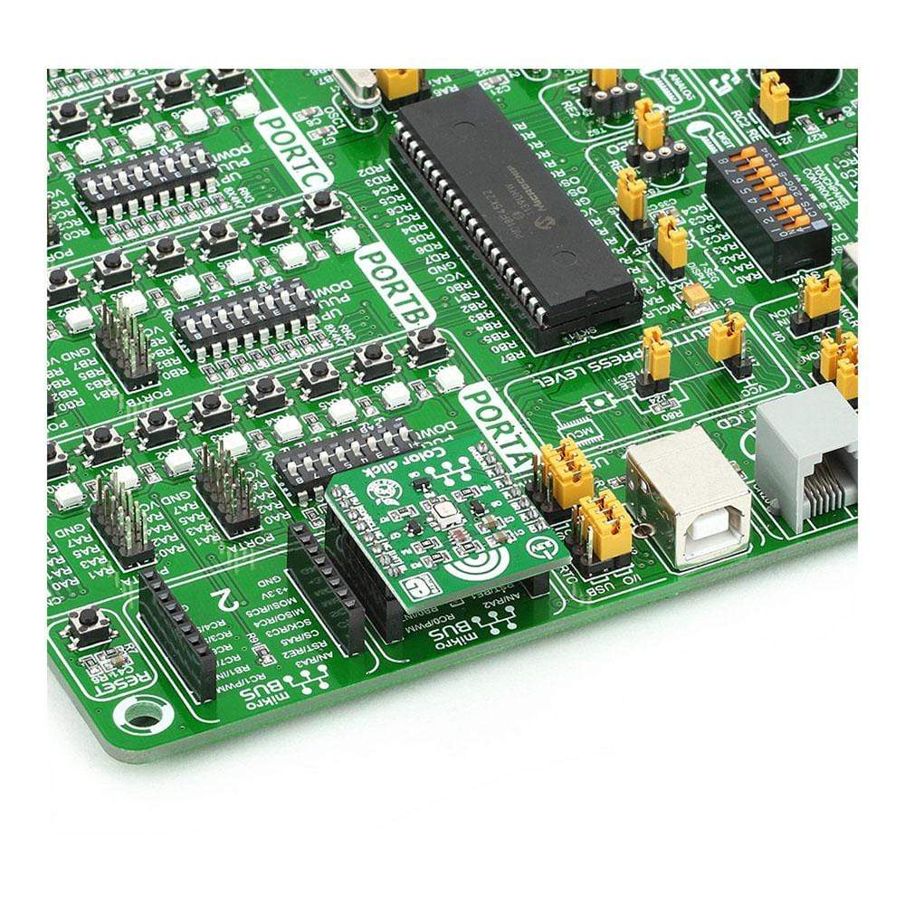
| Compatibility | mikroBUS |
| Click board size | S (28.6 x 25.4 mm) |
| Input Voltage | 3.3V,5V |
PINOUT DIAGRAM
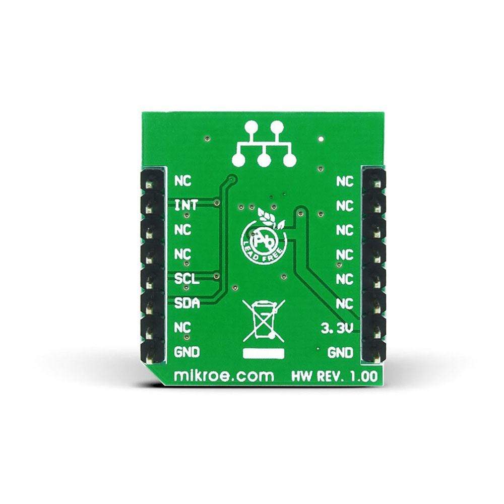
This table shows how the pinout on Color click corresponds to the pinout on the mikroBUS™ socket (the latter shown in the two middle columns).
| Notes | Pin |  |
Pin | Notes | |||
|---|---|---|---|---|---|---|---|
| Red LED | RD | 1 | AN | PWM | 16 | BL | Blue LED |
| NC | 2 | RST | INT | 15 | INT | Interrupt | |
| Green LED | GR | 3 | CS | RX | 14 | NC | |
| NC | 4 | SCK | TX | 13 | NC | ||
| NC | 5 | MISO | SCL | 12 | SCL | I2C Clock | |
| NC | 6 | MOSI | SDA | 11 | SDA | I2C Data | |
| Power supply | 3.3V | 7 | 3.3V | 5V | 10 | 5V | Power supply |
| Ground | GND | 8 | GND | GND | 9 | GND | Ground |
We provide a library for the Color Click Board™ on our LibStock page, as well as a demo application (example), developed using MikroElektronika compilers. The demo can run on all the main MikroElektronika development boards.
Library Description
The library initializes and defines the I2C bus driver and drivers that offer a choice for writing data in the register. The library includes a function for configuration chip for measurement, the function reads one color ratio and functions for light color value is received by calculating RGBC value and conversions in HSL value. The user also has the function color_getColor() which checks the color of the light and functions to enable or disable RGB LED.Key functions:
void color_setLED(uint8_t red, uint8_t green, uint8_t blue)- Functions for set Led lightsfloat color_getColorValue()- Functions for reading the color value in HSLuint8_t color_getColor(float color_value)- Functions for detect colorsfloat color_readColorRatio(uint8_t color)- Functions for reading color ratio
Example Description
The application is composed of three sections :
- System Initialization - Initializes I2C module
- Application Initialization - Initializes driver init and configuration chip for measurement
- Application Task - (code snippet) - Read color and check which color is detected by the sensor. If the color is detected, the detected color message is logged on the USB UART.
void applicationTask() { colorValue = color_getColorValue(); isColor = color_getColor(colorValue); switch(isColor) { case 1: { mikrobus_logWrite("--- Color: ORANGE ", _LOG_LINE); break; } case 2: { mikrobus_logWrite("--- Color: RED ", _LOG_LINE); break; } case 3: { mikrobus_logWrite("--- Color: PINK ", _LOG_LINE); break; } case 4: { mikrobus_logWrite("--- Color: PURPLE ", _LOG_LINE); break; } case 5: { mikrobus_logWrite("--- Color: BLUE ", _LOG_LINE); break; } case 6: { mikrobus_logWrite("--- Color: CYAN ", _LOG_LINE); break; } case 7: { mikrobus_logWrite("--- Color: GREEN ", _LOG_LINE); break; } case 8: { mikrobus_logWrite("--- Color: YELLOW ", _LOG_LINE); break; } default: { break; } } Delay_100ms(); }The full application code, and ready to use projects can be found on our Libstock page.
Other MikroElektronika libraries used in the example:
- I2C
- UART
Additional Notes and Information
Depending on the development board you are using, you may need a USB UART click, USB UART 2 click or RS232 click to connect to your PC, for development systems with no UART to USB interface available on the board. The terminal available in all MikroElektronika compilers, or any other terminal application of your choice, can be used to read the message.
MIKROSDK
The Color Click Board™ is supported with mikroSDK - MikroElektronika Software Development Kit. To ensure proper operation of mikroSDK compliant click board demo applications, mikroSDK should be downloaded from the LibStock and installed for the compiler you are using.
Frequently Asked Questions
Have a Question?
Be the first to ask a question about this.


