Technical Resources
Datasheets, user manuals, drawings and application notes for the debug, programming and test equipment we supply. Search by product, part number or brand. If you can't find a document, contact us and we'll send it.
- All
- Datasheets
- User Manuals
- Quick Start Guides
- Application Notes
- Application Code
- White Papers
- Case Studies
- Drawings
- Schematics
- Brochures
- Presentations
- Service Manuals
| Document | Type | Brand | Version | Download |
|---|---|---|---|---|
| Application Note | Picotest | Rev3 | 3.6 MB | |
| Application Note | Picotest | Rev5 | 3.0 MB | |
| Datasheet | Picotest | 619 KB | ||
| Datasheet | Picotest | REV8 | 894 KB | |
| Datasheet | Picotest | REV3 | 902 KB | |
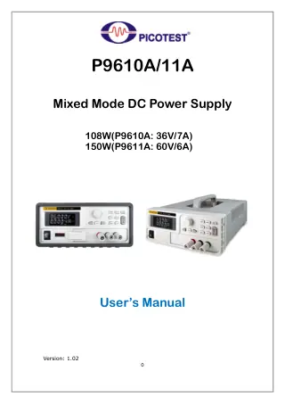
Picotest P9610A P9611A Mixed Mode DC Power SupplyP9611A, P9610AUser Manual v1.02 for Picotest P9610A/11A Mixed Mode DC Power Supply with autoranging capability. P9610A: 108W, 36V/7A output. P9611A: 150W, 60V/6A output. Features remote sensing, OVP/OCP... |
User Manual | Picotest | v1.00 | 5.0 MB |
Picotest P9610A/P9611A Power SupplyP9611A, P9610APicotest P9610A/P9611A Mixed Mode DC Power Supply datasheet. P9610A: 36V/7A/108W, P9611A: 60V/6A/150W. Features autoranging, low noise, fast transient response, remote sensing, and Master/Slave control for versatile... |
Datasheet | Picotest | v1.02 | 7.8 MB |
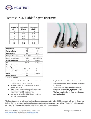
Picotest PDN CablesSMAJ/SMAJ-250, BNCJ/SMAJ-250, BNCJ/BNCJ-250, NJ/BNCJ-250, NJ/NJ-250, SMAJ/NJ-250, SMAJ/SMPMK-250 |
Datasheet | Picotest | 2021 | 216 KB |
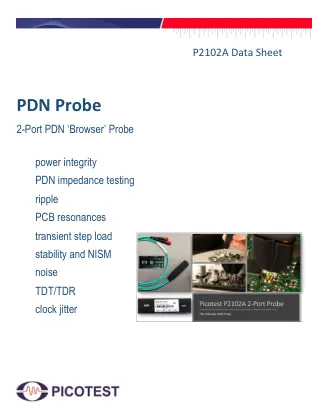
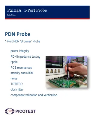
Picotest PDN Probes and Port Saver DC BlockP2102A, P2104A, P2105A |
User Manual | Picotest | 1.7-5 | 5.9 MB |
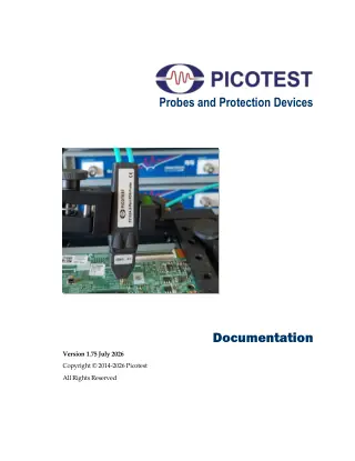
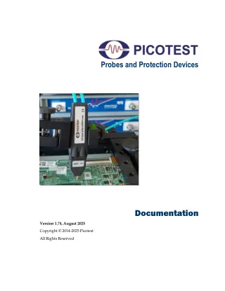
Picotest PDN ProbesP2106A, P2103A, VRTS3, P2105AComprehensive user manual for Picotest PDN Browser probes and protection devices including P2104A, P2102A, P2103A, P2105A, P2106A models. Version 1.74 August 2025. Covers impedance measurement, power... |
User Manual | Picotest | Rev 1.74 | 5.9 MB |
| Brochure | Picotest | Rev4 | 528 KB | |
| Software | Picotest | v2.50 | 4.1 MB | |
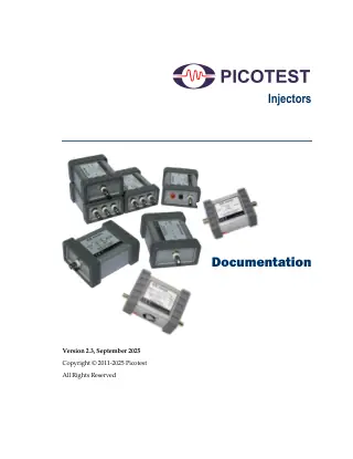
Picotest Signal Injectors Test AdaptersJ2114A, J2181A, J2111B, J2160A, J2113A, J2123A, J2161A, J2140A, J2121A, J2110AComprehensive manual for Picotest Signal Injectors family covering injection transformers, voltage/current injectors, line injectors, and ground loop isolators. Version 2.3 September 2025. Essential test adapters for... |
User Manual | Picotest | Rev 2.3 | 6.2 MB |
| Application Note | Picotest | Rev3 | 858 KB | |
Picotest Test Signal Injectors AccessoriesJ2114A, J2181A, J2111B, J2160A, J2113A, J2123A, J2161A, J2140A, J2121A, J2110APicotest Test Signal Injectors product line including J2100A/J2101A injection transformers, J2110A voltage injector, J2111A/J2112A current injectors, and other analyzer accessories for power supply measurements. No specific... |
Datasheet | Picotest | 3.2 MB | |
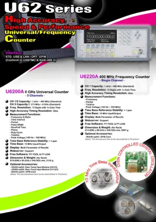
Picotest U62 Series High Accuracy universal/frequency CounterU6200APicotest U62 Series universal/frequency counter data sheet; models U6200A and U6220A. High accuracy timing resolution 40 ps; 10 MHz time-base I/O; USB/LAN with optional GPIB. Version... |
Datasheet | Picotest | v1.04 | 551 KB |
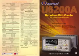
| Brochure | Picotest | 1.7 MB | ||
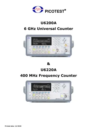
Picotest U6200A & U6220A Universal CountersU6200AComprehensive user manual for PICOTEST U6200A 6GHz Universal Counter and U6220A 400MHz Frequency Counter. Covers operation, measurements, calibration procedures, and remote interface commands. Software version PT-LINK... |
User Manual | Picotest | v1.07 | 2.6 MB |
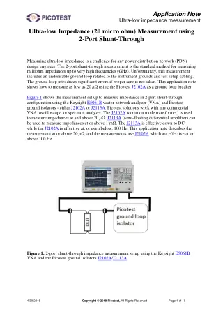
| Application Note | Picotest | 878 KB | ||
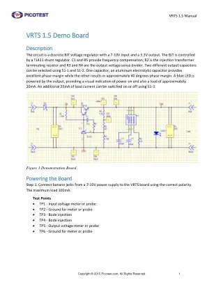
Picotest VRTS 1.5 Demo Board BJT Voltage RegulatorVRTS1.5User manual for the VRTS 1.5 Demo Board version 1.5, a discrete BJT voltage regulator with 7-10V input and 3.3V output. Features TL431 shunt regulator control,... |
User Manual | Picotest | 295 KB | |
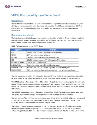
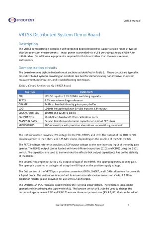
Picotest VRTS3 Distributed System Demo BoardVRTS3The Picotest VRTS3 Distributed System Demo Board is a self-contained, USB-powered training platform designed for comprehensive power integrity measurements. This demonstration board contains eight individual circuit... |
User Manual | Picotest | 507 KB | |
| User Manual | Picotest | V1.0 | 1.7 MB | |
| White Paper | Picotest | 1017 KB | ||
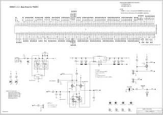
Ronetix BB9261 Base Board v1.2EB9261, SK-PD-EB9261 |
Schematic | Ronetix | v1.2 | 271 KB |
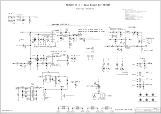
Ronetix BB9G45 Base Board v1.1EB9G45, SK-PD-EB9G45 |
Schematic | Ronetix | v1.1 | 224 KB |
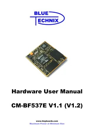
Ronetix CM-BF537E Module HardwareSK-PD-BFIN |
User Manual | Ronetix | V1 | 1.6 MB |
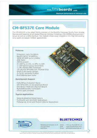
Ronetix CM-BF537E Module OverviewSK-PD-BFIN |
Brochure | Ronetix | 1.0 MB | |
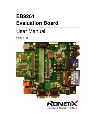
Ronetix EB9261 Evaluation BoardEB9261, SK-PD-EB9261 |
User Manual | Ronetix | 1.2 | 1.3 MB |
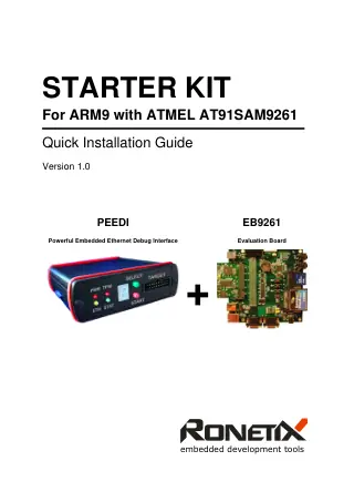
Ronetix EB9261 Starter Kit with PEEDISK-PD-EB9261 |
Quick Start Guide | Ronetix | 1.0 | 154 KB |
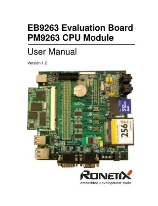
Ronetix EB9263 Evaluation BoardEB9263, SK-PD-EB9263 |
User Manual | Ronetix | 1.2 | 1.3 MB |
Ronetix Eval-BF5xx Board HardwareSK-PD-BFIN |
User Manual | Ronetix | V4.0 | 1.6 MB |
Ronetix Eval-BF5xx Board V4.0SK-PD-BFIN |
Schematic | Ronetix | V4.0 | 68 KB |
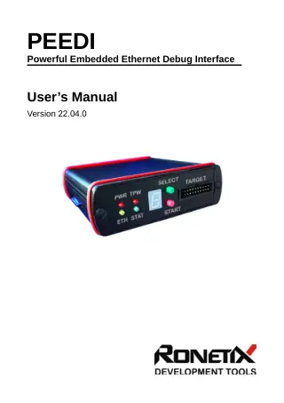
Ronetix PEEDI JTAG/BDM Emulator and Flash ProgrammerPGM-ARM, PD-ARM, PGM-ARM11, PD-ARM11, PGM-AVR32 |
Brochure | Ronetix | Rev. A | 880 KB |
Ronetix PEEDI JTAG/BDM Emulator and Flash ProgrammerPGM-ARM, PD-ARM, PGM-ARM11, PD-ARM11, PGM-AVR32, SW-MULTIPROG |
User Manual | Ronetix | Rev. A (file dated 2022-04-29) | 1.1 MB |
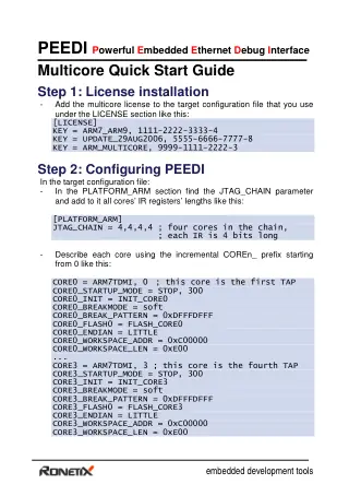
Ronetix PEEDI MulticoreSW-MULTIPROG |
Quick Start Guide | Ronetix | 52 KB | |
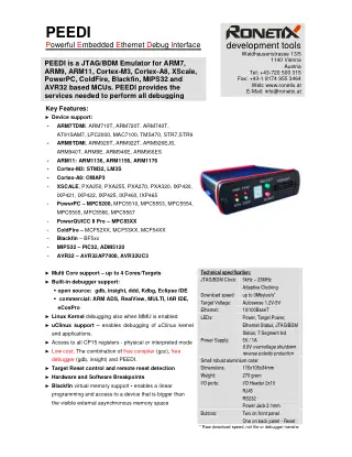
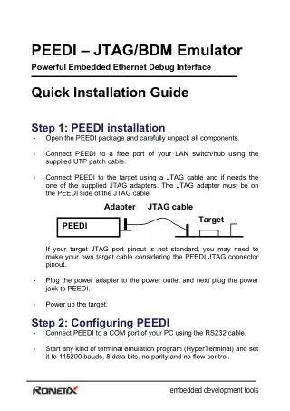
Ronetix PEEDIPGM-ARM, PD-ARM, PGM-ARM11, PD-ARM11, PGM-AVR32 |
Quick Start Guide | Ronetix | 86 KB | |
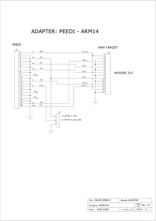
Ronetix PEEDI to ARM-14 AdapterPD-AD-ARM14 |
Schematic | Ronetix | 16 KB | |
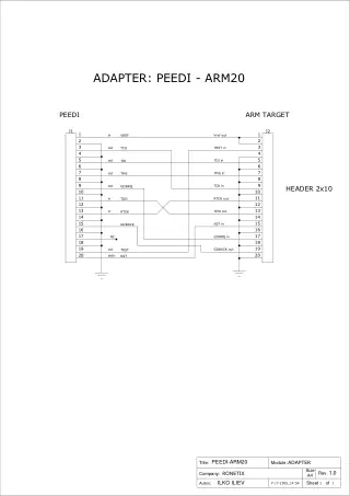
Ronetix PEEDI to ARM-20 AdapterPD-AD-ARM20 |
Schematic | Ronetix | 16 KB | |
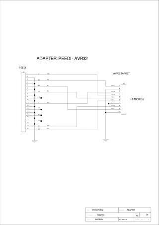
Ronetix PEEDI to AVR32 AdapterPD-AD-AVR32 |
Schematic | Ronetix | 4 KB | |
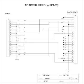
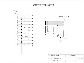
Ronetix PEEDI to BDM-26 ColdFire AdapterPD-AD-COLDFIRE |
Schematic | Ronetix | 5 KB | |
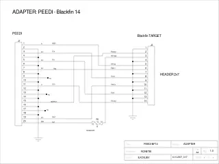
Ronetix PEEDI to Blackfin-14 AdapterPD-AD-BFIN14 |
Schematic | Ronetix | 5 KB | |
| Schematic | Ronetix | 9 KB | ||
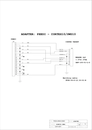
Ronetix PEEDI to Cortex-10 AdapterPD-AD-CORTEX10 |
Schematic | Ronetix | 4 KB | |
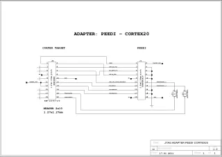
Ronetix PEEDI to Cortex-20 AdapterPD-AD-CORTEX20 |
Schematic | Ronetix | 5 KB | |
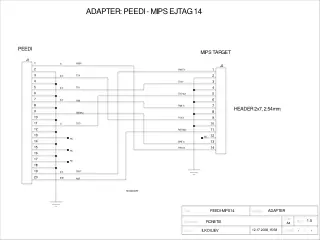
Ronetix PEEDI to MIPS-14 AdapterPD-AD-MIPS32 |
Schematic | Ronetix | 5 KB | |
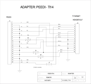
Ronetix PEEDI to TI-14 AdapterPD-AD-TI14 |
Schematic | Ronetix | 6 KB | |
Ronetix PEEDI with EclipsePGM-ARM, PD-ARM, PGM-ARM11, PD-ARM11, PGM-AVR32 |
Application Note | Ronetix | 1.0 | 690 KB |
Ronetix PM9261 CPU ModuleEB9261, SK-PD-EB9261 |
Brochure | Ronetix | 1.9 MB | |
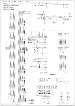
Ronetix PM9261 CPU Module v1.2EB9261, SK-PD-EB9261 |
Schematic | Ronetix | v1.2 | 207 KB |
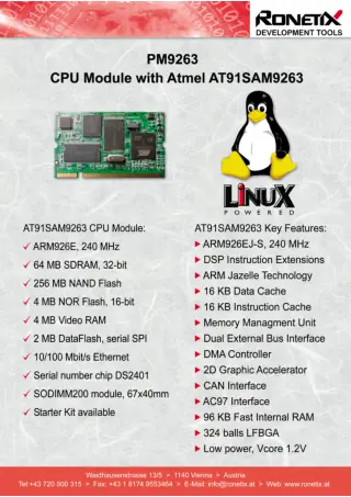
Ronetix PM9263 CPU ModuleEB9263, SK-PD-EB9263 |
Brochure | Ronetix | 1.8 MB | |
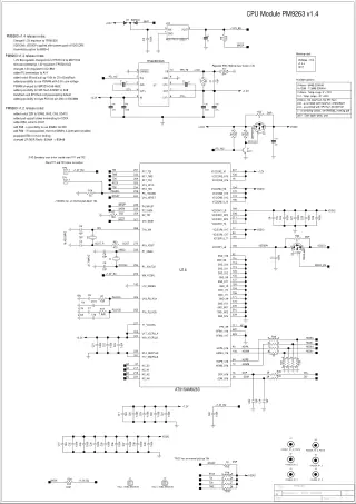
Ronetix PM9263 CPU Module v1.4EB9263, SK-PD-EB9263 |
Schematic | Ronetix | v1.4 | 239 KB |
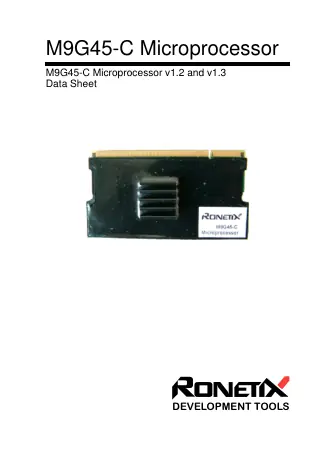
Ronetix PM9G45-C CPU ModulePM9G45-C |
Datasheet | Ronetix | 1.2 | 220 KB |
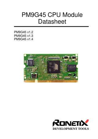
Ronetix PM9G45 CPU ModuleEB9G45, SK-PD-EB9G45 |
Datasheet | Ronetix | 1.2 | 875 KB |
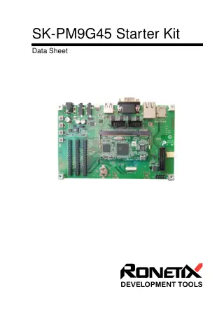
Ronetix SK-PM9G45 Starter KitEB9G45, SK-PD-EB9G45 |
Datasheet | Ronetix | 1.1 MB | |
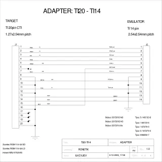
Ronetix TI-14 to TI-20 AdapterPD-AD-TI20-TI14 |
Schematic | Ronetix | 4 KB | |
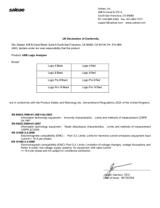
Saleae EU Declaration of ConformitySAL-00111, SAL-00112, SAL-00113, SAL-00114, SAL-00115, SAL-00116 |
Certificate | Saleae | 115 KB | |
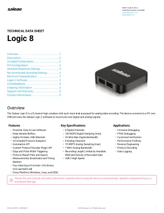
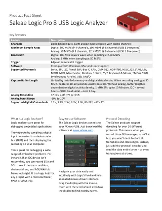
Saleae Logic 8SAL-00111, SAL-00112 |
Datasheet | Saleae | 799 KB | |
Saleae Logic 8 Electromagnetic CompatibilitySAL-00111, SAL-00112 |
Certificate | Saleae | 1.9 MB | |
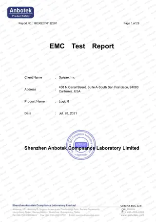
Saleae Logic 8 EMC Test ReportSAL-00111, SAL-00112 |
Other | Saleae | 2.4 MB | |
Saleae Logic 8 Low Voltage SafetySAL-00111, SAL-00112 |
Certificate | Saleae | 306 KB | |
Saleae Logic 8 Low Voltage Test ReportSAL-00111, SAL-00112 |
Other | Saleae | 2.2 MB | |
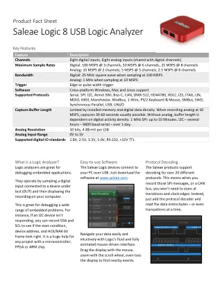
Saleae Logic 8 Product Fact SheetSAL-00111, SAL-00112 |
Brochure | Saleae | 421 KB | |
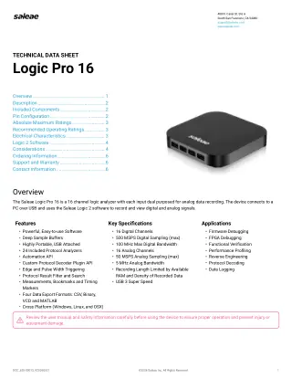
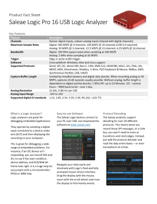
Saleae Logic Pro 16SAL-00115, SAL-00116 |
Datasheet | Saleae | 753 KB | |
Saleae Logic Pro 16 Electromagnetic CompatibilitySAL-00115, SAL-00116 |
Certificate | Saleae | 1.9 MB | |
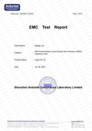
Saleae Logic Pro 16 EMC Test ReportSAL-00115, SAL-00116 |
Other | Saleae | 2.6 MB | |
Saleae Logic Pro 16 Low Voltage SafetySAL-00115, SAL-00116 |
Certificate | Saleae | 306 KB | |
Saleae Logic Pro 16 Low Voltage Test ReportSAL-00115, SAL-00116 |
Other | Saleae | 1.9 MB | |
Saleae Logic Pro 16 Product Fact SheetSAL-00115, SAL-00116 |
Brochure | Saleae | 420 KB | |
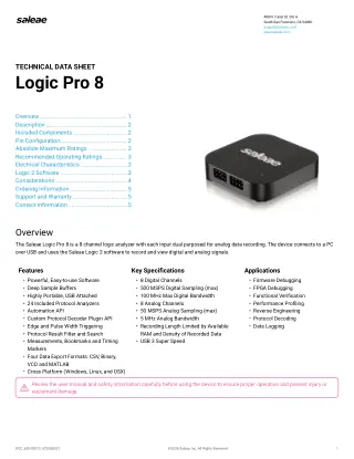
Saleae Logic Pro 8SAL-00113, SAL-00114 |
Datasheet | Saleae | 799 KB | |
Saleae Logic Pro 8 Electromagnetic CompatibilitySAL-00113, SAL-00114 |
Certificate | Saleae | 1.9 MB | |
Saleae Logic Pro 8 EMC Test ReportSAL-00113, SAL-00114 |
Other | Saleae | 2.6 MB | |
Saleae Logic Pro 8 Low Voltage SafetySAL-00113, SAL-00114 |
Certificate | Saleae | 306 KB | |
Saleae Logic Pro 8 Low Voltage Test ReportSAL-00113, SAL-00114 |
Other | Saleae | 2.1 MB | |
Saleae Logic Pro 8 Product Fact SheetSAL-00113, SAL-00114 |
Brochure | Saleae | 421 KB | |
Saleae RoHS DeclarationSAL-00111, SAL-00112, SAL-00113, SAL-00114, SAL-00115, SAL-00116 |
Certificate | Saleae | 89 KB | |
Saleae Statement of VolatilitySAL-00111, SAL-00112, SAL-00113, SAL-00114, SAL-00115, SAL-00116 |
Other | Saleae | 2026-07 | 145 KB |
Saleae UK Declaration of ConformitySAL-00111, SAL-00112, SAL-00113, SAL-00114, SAL-00115, SAL-00116 |
Certificate | Saleae | 44 KB | |
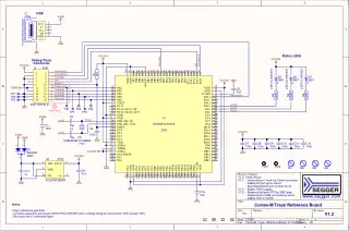
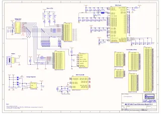
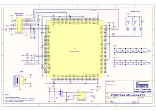
SEGGER Cortex M Trace Reference Board6.68.18Official schematic (v1.3) for SEGGER’s Cortex‑M Trace Reference Board, detailing ETM trace header pinout, power, reset, and test points for fast, reliable trace setup verification. |
Schematic | SEGGER | Rev R1 | 76 KB |
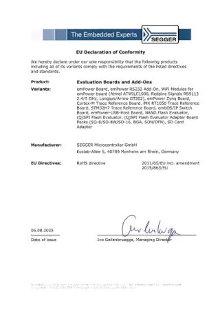
SEGGER Evaluation Boards6.68.18, 6.68.20, 6.20.12, 6.68.19, 6.40.00 |
Certificate | SEGGER | 186 KB | |
SEGGER Flasher 55.07.01 |
User Manual | SEGGER | 2.16 | 444 KB |
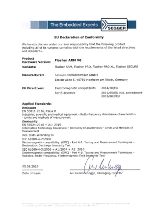
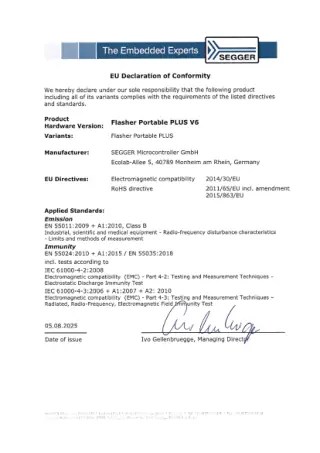
SEGGER Flasher ARM V6 CE Declaration of Conformity5.17.01, 5.17.02, 5.07.01 |
Certificate | SEGGER | 207 KB | |
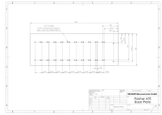
SEGGER Flasher ATE Base Plate Dimensions5.18.01, 5.18.02 |
Drawing | SEGGER | 35 KB | |
SEGGER Flasher ATE5.18.02, 5.18.01Quick setup guide for SEGGER Flasher ATE gang programmer. Covers hardware setup, network configuration, J-Flash project creation, and FTP file transfer for automated production programming environments. |
Quick Start Guide | SEGGER | Rev 1.0 | 480 KB |
SEGGER Flasher ATE5.18.02, 5.18.01User manual for SEGGER Flasher ATE modular gang programmer supporting up to 10 parallel programming channels for high-volume production environments and automated test equipment (ATE) applications. |
User Manual | SEGGER | Rev 1.18 | 2.8 MB |
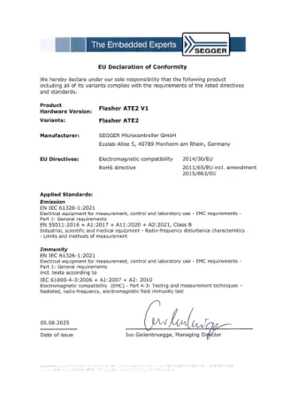
SEGGER Flasher ATE2 CE Declaration of Conformity5.18.01, 5.18.02 |
Certificate | SEGGER | 208 KB | |
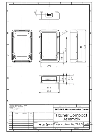
| Drawing | SEGGER | V1.0 | 69 KB | |
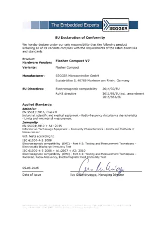
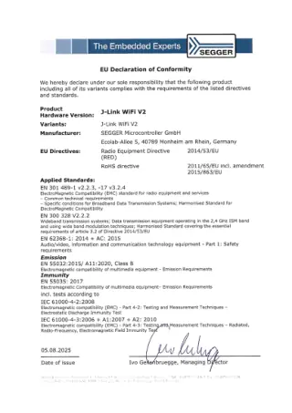
| Certificate | SEGGER | 203 KB | ||
| Drawing | SEGGER | V5.0B | 20 KB | |
| Certificate | SEGGER | 206 KB | ||
| Certificate | SEGGER | 227 KB | ||
| Drawing | SEGGER | 82 KB | ||
SEGGER Flasher Hub-125.01.20 |
User Manual | SEGGER | 9.88 | 70 KB |
| Certificate | SEGGER | 209 KB | ||
SEGGER Flasher Hub-45.01.30 |
User Manual | SEGGER | 1.08 | 69 KB |
| Certificate | SEGGER | 199 KB | ||
| Certificate | SEGGER | 200 KB | ||
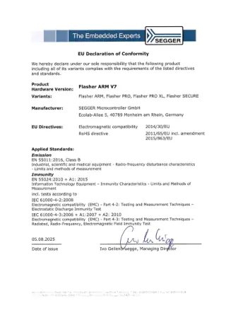
SEGGER Flasher PRO and ARM CE Declaration of Conformity5.17.01, 5.17.02, 5.07.01 |
Certificate | SEGGER | 209 KB | |
SEGGER Flasher PRO5.17.01, 5.17.02 |
User Manual | SEGGER | 2.16 | 414 KB |
SEGGER Flasher5.17.01, 5.17.02, 5.07.01, 5.19.00, 5.16.02 |
User Manual | SEGGER | 9.88 | 2.6 MB |
SEGGER iMXRT1050 Trace Reference Board6.68.19Schematic for the SEGGER iMX RT1050 Trace Reference Board (6.68.19), detailing trace connector, test points and power for ETM and J-Trace setup and validation. |
Schematic | SEGGER | Rev R23 | 57 KB |
SEGGER J-Flash Software5.19.00Official user manual for SEGGER J-Flash v7.92e, the stand-alone flash programming software for ARM, Cortex, and RX microcontrollers. Covers installation, setup, project configuration, and command-line operations. |
User Manual | SEGGER | v7.92e | 639 KB |
SEGGER J-Flash8.08.28, 8.08.13, 8.12.00, 8.16.28 |
User Manual | SEGGER | 9.88 | 641 KB |
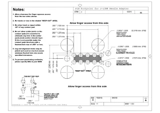
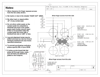
SEGGER J-Link 10-Pin Needle Cable8.06.04Technical PCB footprint drawing for SEGGER J-Link 10-pin needle adapter. Includes precise dimensions, clearance requirements, contact pad specifications, and assembly notes for embedded system debugging applications. |
Drawing | SEGGER | A | 907 KB |
SEGGER J-Link 6-Pin Needle Cable8.06.16Technical PCB footprint drawing for SEGGER J-Link 6-pin needle adapter with dimensional specs, layout guidelines, and Tag Connect TC2030-IDC compatibility for programming/debugging. |
Drawing | SEGGER | Rev 12 | 129 KB |
SEGGER J-Link Adapters8.06.00, 8.06.01, 8.06.02, 8.06.03, 8.06.04, 8.06.06, 8.06.08, 8.06.10, 8.06.11, 8.06.12, 8.06.13, 8.06.14, 8.06.15, 8.06.16, 8.06.17, 8.06.18, 8.06.19, 8.06.20, 8.06.21, 8.06.22, 8.06.23, 8.06.24, 8.06.25, 8.06.26, 8.06.27, 8.06.28, 8.06.29, 8.06.30, 8.06.32, 8.06.33, 8.06.35, 8.06.36, 8.06.37, 8.06.39, 8.06.41, 8.06.42, 8.06.09, 8.06.38, 8.06.40, 8.06.07 |
Certificate | SEGGER | 317 KB | |
SEGGER J-Link and J-Trace8.12.00, 8.16.28, 8.14.28, 8.08.28, 8.08.00, 8.19.28, 8.19.00, 8.12.28, 8.08.13, 8.20.00, 8.18.00, 8.22.00, 8.24.00 |
User Manual | SEGGER | 9.88 | 4.1 MB |
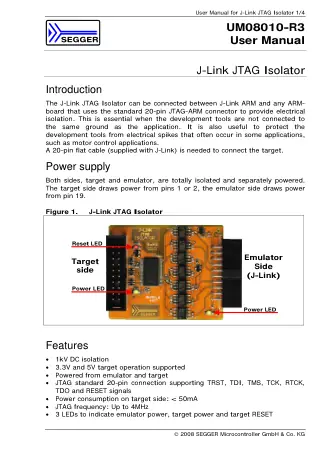
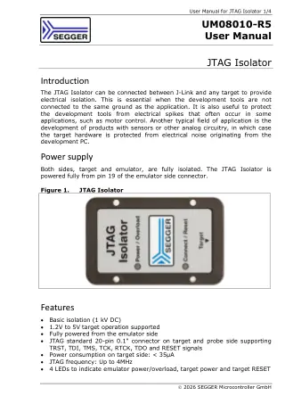
SEGGER J-Link ARM JTag Isolator8.07.00SEGGER J-Link JTAG Isolator user manual providing setup instructions, connection diagrams, and electrical specifications. Features 1kV DC isolation, 3.3V/5V target support, and up to 4MHz JTAG... |
User Manual | SEGGER | 89 KB | |
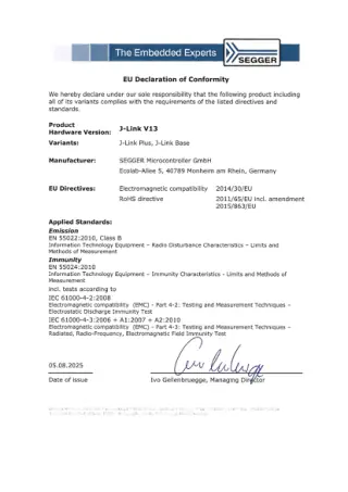
SEGGER J-Link BASE and PLUS CE Declaration of Conformity8.08.00, 8.08.28 |
Certificate | SEGGER | 197 KB | |
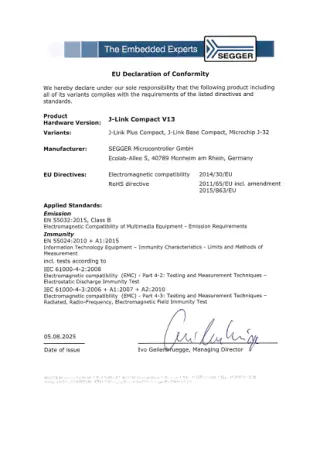
SEGGER J-Link Compact CE Declaration of Conformity8.19.28, 8.19.00 |
Certificate | SEGGER | 199 KB | |
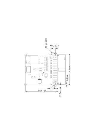
SEGGER J-Link Compact Dimensions8.19.28, 8.19.00 |
Drawing | SEGGER | 9 KB | |
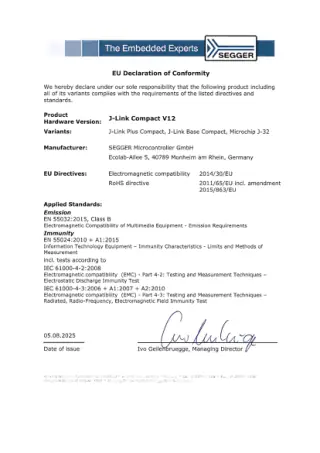
SEGGER J-Link Compact V12 CE Declaration of Conformity8.19.28, 8.19.00 |
Certificate | SEGGER | 203 KB | |
SEGGER J-Link JTAG Isolator8.07.00 |
User Manual | SEGGER | 331 KB | |
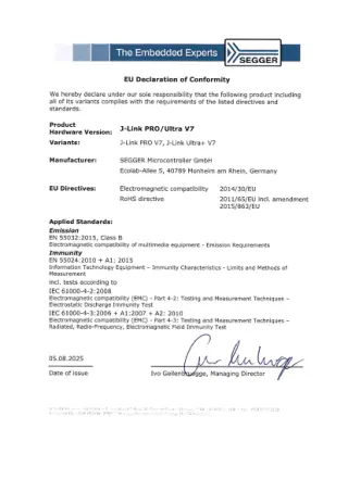
SEGGER J-Link PRO and ULTRA+ CE Declaration of Conformity8.12.00, 8.16.28 |
Certificate | SEGGER | 199 KB | |
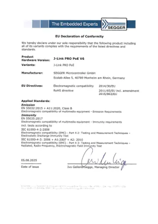
| Certificate | SEGGER | 193 KB | ||
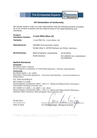
SEGGER J-Link PRO V6 and ULTRA V6 CE Declaration of Conformity8.12.00, 8.16.28 |
Certificate | SEGGER | 197 KB | |
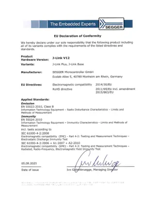
SEGGER J-Link V12 CE Declaration of Conformity8.08.00, 8.08.28 |
Certificate | SEGGER | 198 KB | |
| Certificate | SEGGER | 242 KB | ||
SEGGER J-Trace PRO8.20.00, 8.18.00, 8.22.00, 8.24.00 |
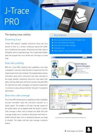
Brochure | SEGGER | 283 KB | |
SEGGER J-Trace PRO CE Declaration of Conformity8.20.00, 8.18.00, 8.22.00, 8.24.00 |
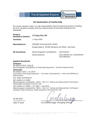
Certificate | SEGGER | 195 KB | |
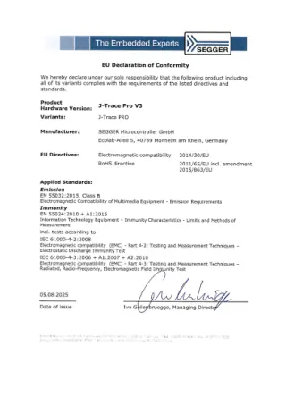
SEGGER J-Trace PRO V3 CE Declaration of Conformity8.20.00, 8.18.00, 8.22.00, 8.24.00 |
Certificate | SEGGER | 198 KB | |
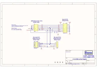
SEGGER Microchip AdapterTechnical schematic for SEGGER J-Link Microchip Adapter showing 20-pin debug probe connector, 14-pin MIPS debug header, and RJ12/PICkit connections. Features JTAG signals (TDI, TMS, TCK, TDO),... |
Schematic | SEGGER | Rev 5.04 | 16 KB |
SEGGER Ozone Debugger8.12.00, 8.16.28, 8.14.28, 8.08.28, 8.08.00, 8.19.28, 8.19.00, 8.12.28, 8.20.00, 8.18.00, 8.22.00, 8.24.00 |
User Manual | SEGGER | 3.50 | 4.2 MB |
SEGGER Ozone Software8.08.00Comprehensive user manual for SEGGER Ozone v3.30b debugger and performance analyzer. Features C/C++/Rust debugging, instruction tracing, code profiling, and system analysis for embedded applications with J-Link... |
User Manual | SEGGER | Rev 3.30 | 3.9 MB |
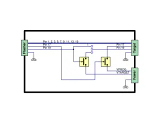
SEGGER Programming Voltage Adapter8.06.30High-voltage programming adapter for SEGGER debuggers. Provides dual voltage control (4-20V, 500mA max) for targets requiring voltages beyond 5V. Features standard 20-pin connectors and direct J-Link/Flasher... |
Schematic | SEGGER | 140 KB | |
| Certificate | SEGGER | 320 KB | ||
SEGGER STM32H7 Trace Reference Board6.68.20SEGGER STM32H7 Trace Reference Board schematic featuring STM32H743ZIT6 ARM Cortex-M7 MCU with ETM trace support, USB connectivity, debug headers, and test points for instruction tracing and... |
Schematic | SEGGER | Rev R1 | 43 KB |
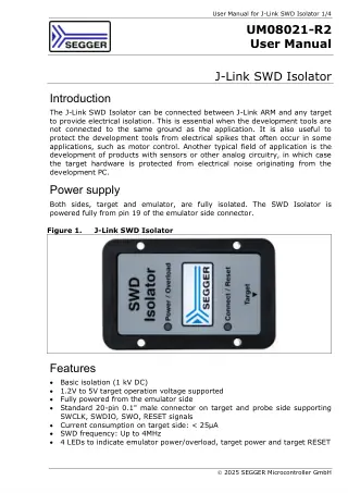
SEGGER SWD Isolator Adapter8.07.01 |
User Manual | SEGGER | 225 KB | |
SEGGER SystemView8.08.00Complete user guide for SEGGER SystemView v3.52 - real-time recording and analysis toolkit for embedded systems runtime behavior. Covers installation, configuration, and API reference for visual... |
User Manual | SEGGER | Rev 3.52 | 1.8 MB |
SEGGER SystemView8.12.00, 8.16.28, 8.14.28, 8.08.28, 8.08.00, 8.19.28, 8.19.00, 8.12.28, 8.20.00, 8.18.00, 8.22.00, 8.24.00 |
User Manual | SEGGER | 4.10 | 2.2 MB |
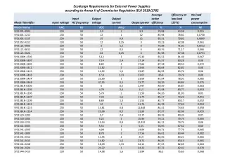
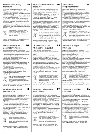
Sunny Computer Sunny Power Supplies Ecodesign DeclarationMIKROE-2183, MIKROE-2184, MIKROE-2185, MIKROE-2193 |
Certificate | Sunny Computer | 687 KB | |
Sunny Computer Sunny Power Supplies Manual and Safety InstructionsMIKROE-2183, MIKROE-2184, MIKROE-2185, MIKROE-2193 |
User Manual | Sunny Computer | 5.6 MB | |
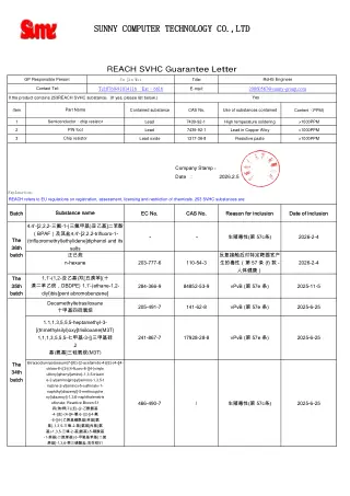
Sunny Computer Sunny Power Supplies REACH DeclarationMIKROE-2183, MIKROE-2184, MIKROE-2185, MIKROE-2193 |
Certificate | Sunny Computer | 792 KB | |
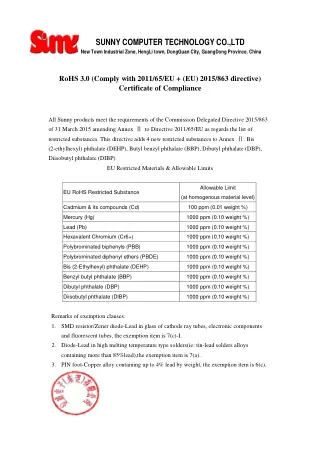
Sunny Computer Sunny Power Supplies RoHS DeclarationMIKROE-2183, MIKROE-2184, MIKROE-2185, MIKROE-2193 |
Certificate | Sunny Computer | 68 KB | |
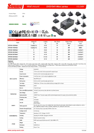
Sunny Computer Sunny SYS1541-Wxx Wall Mount Power SuppliesMIKROE-2183, MIKROE-2184, MIKROE-2185, MIKROE-2193 |
Datasheet | Sunny Computer | 1.3 MB | |
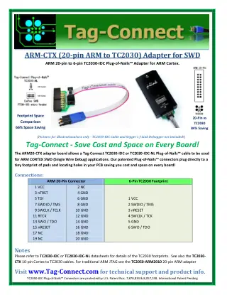
Tag-Connect ARM20-CTX AdapterARM20-CTX, ARM20-CTX-M |
Datasheet | Tag-Connect | 570 KB | |
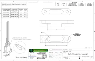
Tag-Connect Connector Mount FixturesTC2030-MOUNT, TC2050-MOUNT, TC2070-MOUNT |
Drawing | Tag-Connect | r02 | 375 KB |
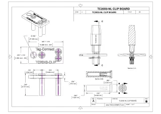
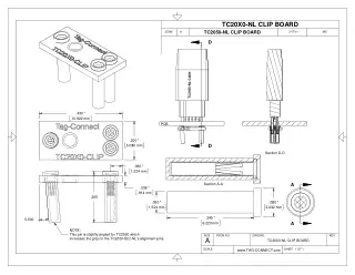
Tag-Connect data-sheet-tag-connect-tc2030-CLIPTC2030-CLIP, TC2030-CLIP-3PACK |
Datasheet | Tag-Connect | B | 157 KB |
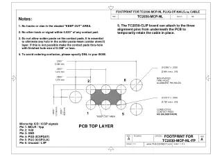
Tag-Connect data-sheet-tag-connect-tc2030-MCP-nl PCB Footprint 5TC2030-MCP, TC2030-MCP-NL, TC2030-MCP-SOFT |
Datasheet | Tag-Connect | A | 208 KB |
Tag-Connect data-sheet-tag-connect-tc2050-CLIP25TC2050-CLIP, TC2050-CLIP-3PACK |
Datasheet | Tag-Connect | 77 KB | |
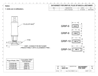
Tag-Connect GRIP RetainersGRIP-6-3-Pack, GRIP-10-3-Pack, GRIP-14-3-Pack, GRIP-10 |
Datasheet | Tag-Connect | 2025-05 | 85 KB |
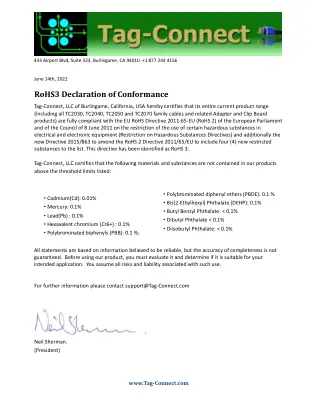
| Certificate | Tag-Connect | Jan 2025 | 123 KB | |
| Certificate | Tag-Connect | 94 KB | ||
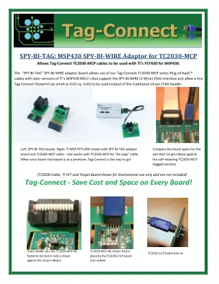
Tag-Connect SPY-BI-TAG MSP430 AdapterSPY-BI-TAG |
Datasheet | Tag-Connect | 1.3 MB | |
Tag-Connect TC-RENESAS AdapterTC-RENESAS |
Datasheet | Tag-Connect | 423 KB | |
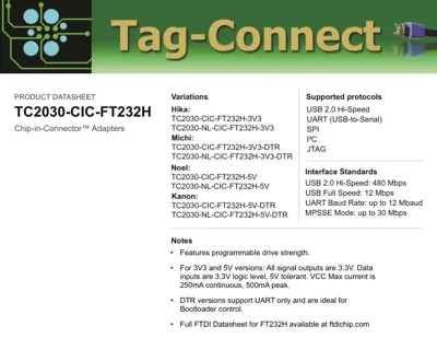
Tag-Connect TC2030-CIC-FT232H Chip-in-ConnectorTC2030-CIC-FT232H-3V3, TC2030-CIC-FT232H-3V3-DTR, TC2030-CIC-FT232H-5V, TC2030-CIC-FT232H-5V-DTR, TC2030-NL-CIC-FT232H-3V3, TC2030-NL-CIC-FT232H-3V3-DTR, TC2030-NL-CIC-FT232H-5V, TC2030-NL-CIC-FT232H-5V-DTR |
Datasheet | Tag-Connect | A | 1.0 MB |
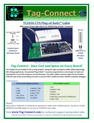
Tag-Connect TC2030-CTX Cortex CablesTC2030-CTX, TC2030-CTX-NL, TC2030-CTX-20, TC2030-CTX-20-NL, TC2030-CTX-ST14, TC2030-CTX-NL-ST14, TC2030-CTX-SOFT |
Datasheet | Tag-Connect | 929 KB | |
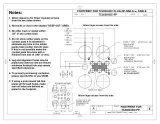
Tag-Connect TC2030-IDC Legged CablesTC2030-IDC, TC2030-IDC-10, TC2030-ALT, TC2030-ICESPI, TC2030-CIC-FT232H-3V3, TC2030-CIC-FT232H-3V3-DTR, TC2030-CIC-FT232H-5V, TC2030-CIC-FT232H-5V-DTR, TC2030-FTDI-C232HD-DDHSP-0-DTR, TC2030-FTDI-C232HD-EDHSP-0-DTR, TC2030-FTDI-TTL-232RG-VREG1V8, TC2030-FTDI-TTL-232RG-VREG3V3, TC2030-FTDI-TTL-232RG-VSW3V3, TC2030-FTDI-TTL-232RG-VSW5V, TC2030-IDC-050, TC2030-MCP-SOFT |
Datasheet | Tag-Connect | Rev B | 156 KB |
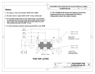
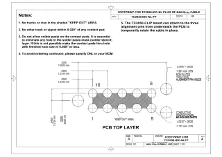
Tag-Connect TC2030-IDC-NL No-Legs CablesTC2030-IDC-NL, TC2030-IDC-NL-10, TC2030-ALT-NL, TC2030-ICESPI-NL, TC2030-NL-CIC-FT232H-3V3, TC2030-NL-CIC-FT232H-3V3-DTR, TC2030-NL-CIC-FT232H-5V, TC2030-NL-CIC-FT232H-5V-DTR, TC2030-NL-FTDI-C232HD-DDHSP-0-DTR, TC2030-NL-FTDI-C232HD-EDHSP-0-DTR, TC2030-NL-FTDI-TTL-232RG-VREG1V8, TC2030-NL-FTDI-TTL-232RG-VREG3V3, TC2030-NL-FTDI-TTL-232RG-VSW3V3, TC2030-NL-FTDI-TTL-232RG-VSW5V, TC2030-IDC-NL-050 |
Datasheet | Tag-Connect | Rev B | 74 KB |
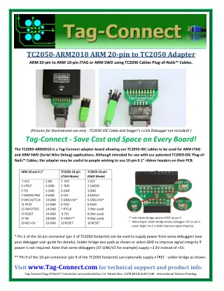
Tag-Connect TC2050-2x10 AdapterTC2050-2X10 |
Datasheet | Tag-Connect | 263 KB | |
Tag-Connect TC2050-ARM2010 AdapterTC2050-ARM2010, TC2050-ARM2010-M |
Datasheet | Tag-Connect | 2021 | 625 KB |
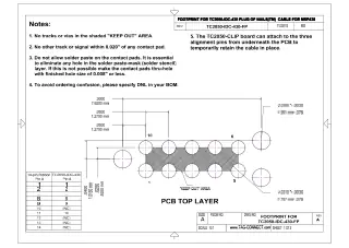
Tag-Connect TC2050-IDC-430 MSP430 Legged CableTC2050-IDC-430 |
Datasheet | Tag-Connect | A | 1.8 MB |
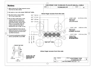
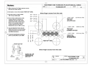
Tag-Connect TC2050-IDC Legged CablesTC2050-IDC, TC2050-IDC-M, TC2050-IDC-050, TC2050-IDC-050-ALL, TC2050-IDC-050-ALL-20, TC2050-IDC-050-ALL-SOFT, TC2050-IDC-050-ALL-LEMTA-SOFT, TC2050-IDC-LONGLEGS, TC2050-IDC-SOFT |
Datasheet | Tag-Connect | A | 1.2 MB |
Tag-Connect TC2050-IDC-NL-430 MSP430 No-Legs CableTC2050-IDC-NL-430 |
Datasheet | Tag-Connect | 1.1 MB | |
Tag-Connect TC2050-IDC-NL No-Legs CablesTC2050-IDC-NL, TC2050-IDC-NL-M, TC2050-IDC-NL-050, TC2050-IDC-NL-050-ALL-20 |
Datasheet | Tag-Connect | 1.1 MB | |
Tag-Connect TC2050-MINIHDMI CablesTC2050-MINIHDMI, TC2050-MINIHDMI-NL |
Datasheet | Tag-Connect | 263 KB | |
Tag-Connect TC2050-XILINX AdapterTC2050-XILINX, TC2050-XILINX-M |
Datasheet | Tag-Connect | 425 KB | |
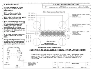
Tag-Connect TC2070-IDC Legged CablesTC2070-IDC, TC2070-IDC-050, TC2070-IDC-2MM, TC2070-IDC-SOFT |
Datasheet | Tag-Connect | 2.1 MB | |
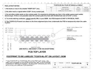
Tag-Connect TC2070-IDC-NL No-Legs CablesTC2070-IDC-NL, TC2070-IDC-NL-050, TC2070-IDC-NL-2MM |
Datasheet | Tag-Connect | 1.3 MB | |
| Certificate | Tag-Connect | 7 Jul 2023 | 122 KB | |
Tag-Connect user-manual-tag-connect-TC2030-TC2050-CLIPSPY-BI-TAG, TC2050-ARM2010, TC2050-ARM2010-M, TC2050-CLIP, TC2050-CLIP-3PACK |
User Manual | Tag-Connect | 439 KB | |
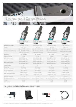
TESTEC Current Probes Comparison Chart15322, 15355, 15377, 15399 |
Brochure | Testec | 1.6 MB | |
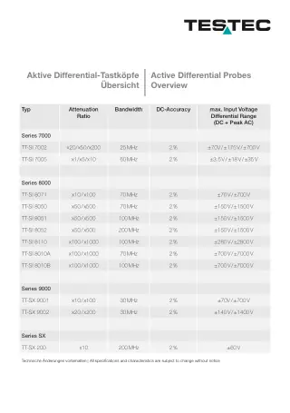
TESTEC Differential Probes Comparison Chart15175, 15176, 15411, 15412, 15402, 15403, 15404, 15401, 15410, 15601, 15602, 15635 |
Brochure | Testec | 2022 | 1.4 MB |
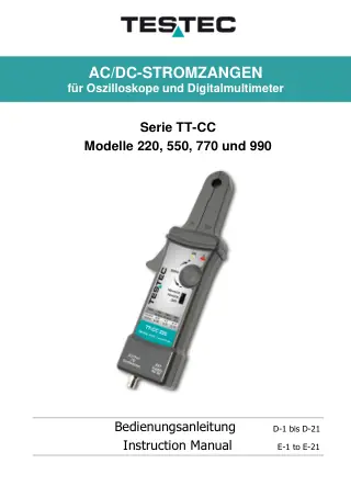
TESTEC TT-CC Series AC/DC Current Probes15322, 15355, 15377, 15399 |
User Manual | Testec | 2023 | 1.2 MB |
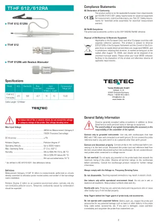
TESTEC TT-HF 612 and 612RA Oscilloscope Probes12070, 12070-RA |
User Manual | Testec | 925 KB | |
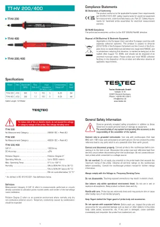
TESTEC TT-HV 200 and 400 High Voltage Probes13040, 13020 |
User Manual | Testec | 889 KB | |
| User Manual | Testec | 2024 | 173 KB | |
| User Manual | Testec | 2024 | 458 KB | |
| User Manual | Testec | 2024 | 2.2 MB | |
| User Manual | Testec | 2024 | 88 KB | |
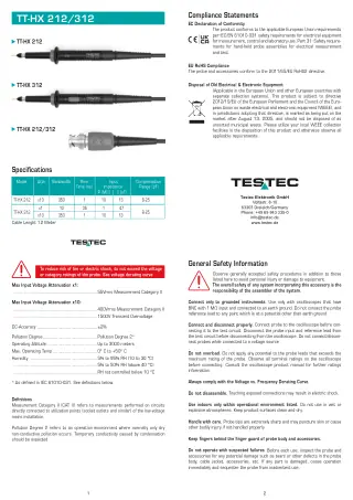
TESTEC TT-HX 212 and 312 Oscilloscope Probes12110, 12120 |
User Manual | Testec | 794 KB | |
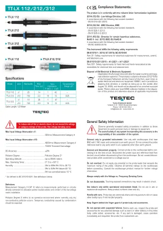
TESTEC TT-LX 112 212 and 312 Oscilloscope Probes10100, 10110, 10120 |
User Manual | Testec | 824 KB | |
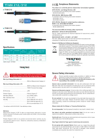
TESTEC TT-MX 212 and 312 Oscilloscope Probes11110, 11120 |
User Manual | Testec | 836 KB | |
| User Manual | Testec | 2024 | 719 KB | |
| User Manual | Testec | 2024 | 691 KB | |
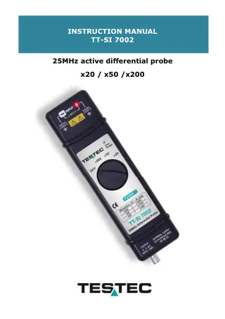
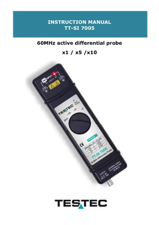
TESTEC TT-SI 8000 Series Differential Probes15411, 15412, 15402, 15403, 15404, 15401, 15410 |
User Manual | Testec | 2.7 MB | |
| User Manual | Testec | 881 KB | ||
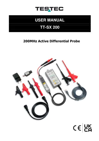
TESTEC TT-SX 9001 and 9002 Differential Probes15601, 15602 |
Datasheet | Testec | 264 KB | |
TESTEC TT-SX 900x Series Differential Probes15601, 15602 |
User Manual | Testec | 697 KB | |
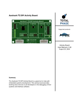
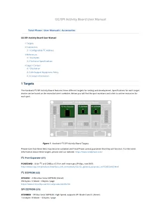
Total Phase Aardvark I²C/SPI Activity BoardTP240310Complete user manual for the Aardvark I²C/SPI Activity Board featuring three target devices: I²C Port Expander (PCA9554AD), I²C EEPROM (AT24C02), and SPI EEPROM (AT25080A). Essential guide... |
User Manual | Total Phase | v1.00 | 269 KB |
Total Phase Aardvark I2C/SPI Host AdapterTP240141, TP120112, TP120212 |
Datasheet | Total Phase | 232 KB | |
Total Phase Aardvark I2C/SPI Host Adapter USB InterfaceTP240141Official datasheet for the Total Phase Aardvark I2C/SPI Host Adapter (TP240141). Fast USB-to-I2C/SPI interface supporting master/slave operation, speeds up to 800 kHz I2C and 8 MHz... |
Datasheet | Total Phase | 254 KB | |
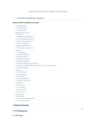
Total Phase Aardvark I2C/SPI Host AdapterTP240141Complete user manual for Total Phase Aardvark I2C/SPI Host Adapter v5.15. Covers hardware specifications, software installation, API documentation, and programming examples for Windows, Linux, and Mac... |
User Manual | Total Phase | v5.15 | 525 KB |
Total Phase Aardvark I2C/SPI Host AdapterTP240141, TP120112, TP120212 |
User Manual | Total Phase | 1.1 MB | |
| Case Study | Total Phase | 570 KB | ||
Total Phase Aardvark OEM I2C Host AdapterLow-cost USB-to-I2C master interface for embedded system prototyping, production testing, and evaluation board bundling. Supports speeds up to 125 kHz with 4 GPIOs available. Includes Aardvark... |
Datasheet | Total Phase | 76 KB | |
Total Phase Aardvark OEM SPI Host AdapterTechnical specifications for the USB-to-SPI master adapter with speeds up to 1 Mbps. Features GPIO pins and cross-platform API support for Windows, Linux, and Mac OS... |
Datasheet | Total Phase | 647 KB | |
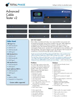
Total Phase Advanced Cable TesterComprehensive specifications for the Advanced Cable Tester v2, featuring signal integrity testing up to 12.8 Gbps, USB PD 3.0 compatibility, E-Marker verification, and support for USB,... |
Datasheet | Total Phase | v2 | 1.6 MB |
Total Phase Advanced Cable TesterComprehensive guide for operating and troubleshooting the Total Phase Advanced Cable Tester v2.0.0. Covers setup, test procedures, and maintenance best practices to ensure accurate USB and... |
User Manual | Total Phase | v2 | 1.5 MB |
| White Paper | Total Phase | 442 KB | ||
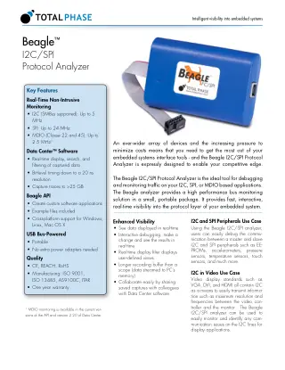
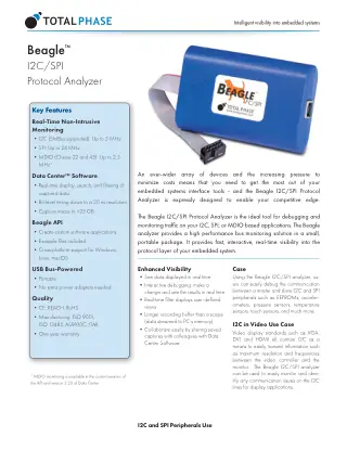
Total Phase Beagle I2C/SPI Protocol AnalyserTP320121The Beagle™ I2C/SPI Protocol Analyzer v1.4 provides non-intrusive, high-speed (up to 12.5 MHz) real-time monitoring and analysis of I2C and SPI buses across Windows, macOS, and... |
Datasheet | Total Phase | Rev 2.20 | 366 KB |
| Datasheet | Total Phase | 252 KB | ||
Total Phase Beagle Protocol AnalyzerTP320121, TP320510, TP320221, TP322610, TP323610 |
User Manual | Total Phase | 4.0 MB | |
Total Phase Beagle USB 12 Protocol AnalyserTP320221Data Sheet for Beagle USB 12 Protocol Analyzer, version 1.0. High-speed USB 1.2 protocol capture and real-time monitoring tool. |
Datasheet | Total Phase | 543 KB | |
| Datasheet | Total Phase | 226 KB | ||
| Case Study | Total Phase | 893 KB | ||
| Case Study | Total Phase | 661 KB | ||
Total Phase Beagle USB 480 Power Protocol AnalyzerTP323610Non-intrusive USB 2.0 power and protocol monitor, version 2.0. Tracks both power consumption and bus traffic for comprehensive USB debugging. |
Datasheet | Total Phase | 240 KB | |
| Datasheet | Total Phase | 190 KB | ||
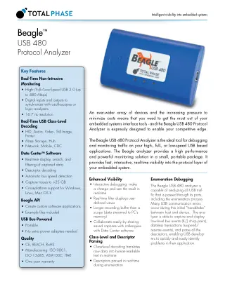
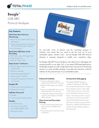
Total Phase Beagle USB 480 Protocol AnalyzerTP320510USB 2.0 protocol analyzer offering non-intrusive packet-level capture and decode. Supports up to 480 Mbps data rates. Version 1.3. |
Datasheet | Total Phase | 574 KB | |
| Datasheet | Total Phase | 225 KB | ||
| Case Study | Total Phase | 192 KB | ||
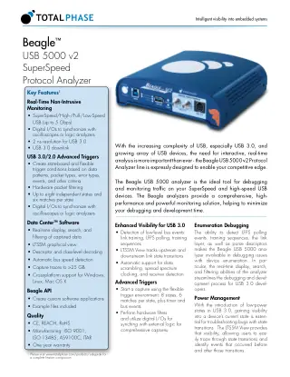
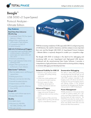
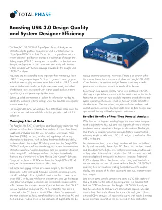
Total Phase Beagle USB 5000 Superspeed Protocol AnalyzerTP322610Data Sheet detailing the features, specifications, and performance metrics of the Beagle USB 5000 Superspeed Protocol Analyzer; version 1.2. |
Datasheet | Total Phase | 876 KB | |
| Datasheet | Total Phase | 245 KB | ||
Total Phase Beagle USB Analyzers at Linus Tech Tips LabsTP320510, TP322610 |
Case Study | Total Phase | 987 KB | |
| White Paper | Total Phase | v1.00 | 89 KB | |
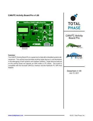
Total Phase CAN/I2C Activity Board Pro Development ToolTP360210Technical specifications for the CAN/I2C Activity Board Pro v1.00, a development tool with working target devices for CAN nodes and I2C slaves. Compatible with Komodo CAN... |
Datasheet | Total Phase | 1.00 | 399 KB |
| User Manual | Total Phase | 867 KB | ||
Total Phase Cheetah GUI SoftwareTP280121 |
User Manual | Total Phase | 1.12 | 514 KB |
Total Phase Cheetah SPI Host AdapterTP280121The Cheetah SPI Host Adapter (R20191121) is a fast and powerful USB to SPI host adapter capable of communicating at up to 40+ MHz. It is... |
Datasheet | Total Phase | 258 KB | |
Total Phase Cheetah SPI Host AdapterTP280121This User Manual provides comprehensive documentation for the Cheetah SPI Host Adapter, a USB 2.0 device supporting SPI communication at speeds from 100 KHz to 40... |
User Manual | Total Phase | v3.08 | 393 KB |
| User Manual | Total Phase | 732 KB | ||
Total Phase Control Center Serial SoftwareTP240141, TP120112, TP120212, TP280121, TP500110 |
User Manual | Total Phase | 4.3.0 | 1.4 MB |
Total Phase Control Center SoftwareTP240141, TP280121Complete user guide for Total Phase Control Center Serial software v3.83, providing graphical interface access to I²C, SPI, and GPIO functions for Promira Serial Platform and... |
User Manual | Total Phase | v3.83 | 952 KB |
Total Phase Data Center SoftwareTP320510, TP320221, TP322610, TP323610 |
User Manual | Total Phase | 6.73 | 6.0 MB |
Total Phase Data Center Software v6.73 Protocol AnalyzerTP320221, TP360110, TP322610, TP320510, TP320121Complete user manual for Total Phase Data Center v6.73.000 software - graphical interface for Beagle analyzers, Power Delivery analyzers, Promira platforms, and Komodo interfaces. Monitor USB,... |
User Manual | Total Phase | Rev 6.73 | 5.4 MB |
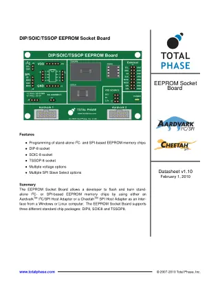
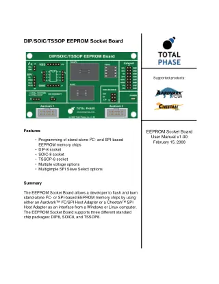
Total Phase DIP/SOIC/TSSOP EEPROM Socket BoardTechnical datasheet for Total Phase EEPROM Socket Board v1.00. Program I2C and SPI EEPROMs in DIP8, SOIC8, and TSSOP8 packages using Aardvark or Cheetah adapters. Features... |
Datasheet | Total Phase | 1.10 | 2.6 MB |
| User Manual | Total Phase | v1.00 | 675 KB | |
Total Phase EEPROM Socket BoardTP240510 |
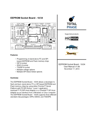
User Manual | Total Phase | v1.00 | 829 KB |
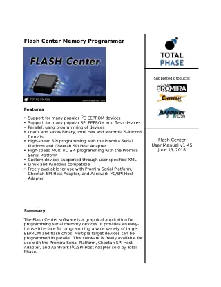
Total Phase Flash Center Memory ProgrammerTP240141, TP280121Complete user manual for Total Phase Flash Center v1.45 software. Learn to program I²C EEPROM, SPI EEPROM and SPI flash devices with Promira Serial Platform, Cheetah... |
User Manual | Total Phase | v1.45 | 567 KB |
Total Phase Flash Center SoftwareTP240510, TP240511, TP280310, TP282310, TP280210 |
User Manual | Total Phase | 1.45 | 983 KB |
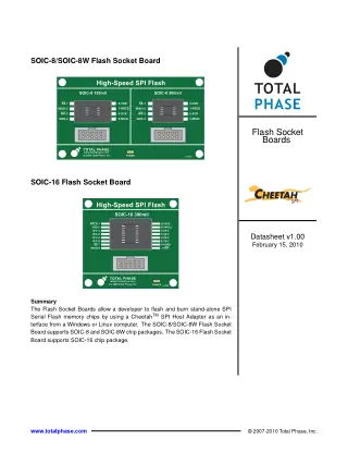
Total Phase Flash Socket BoardTP240511Short Description: Official datasheet v1.00 for Total Phase SOIC-8/SOIC-8W and SOIC-16 Flash Socket Boards. Compatible with Cheetah SPI Host Adapter for programming stand-alone SPI Serial Flash... |
Datasheet | Total Phase | 1.00 | 983 KB |
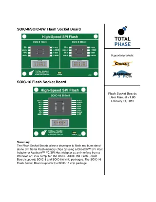
Total Phase Flash Socket Boards Programming GuideTP240511Comprehensive v1.00 user manual for Total Phase SOIC-8/SOIC-8W and SOIC-16 Flash Socket Boards. Learn setup, programming procedures, and compatibility with Cheetah/Aardvark adapters for SPI Serial Flash... |
User Manual | Total Phase | 1.00 | 630 KB |
| User Manual | Total Phase | v1.00 | 641 KB | |
| User Manual | Total Phase | 1.01 | 204 KB | |
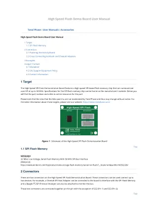
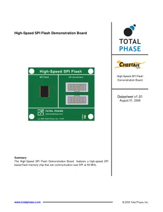
Total Phase High-Speed SPI Flash Demonstration BoardTP280210Complete technical specifications for Total Phase's High-Speed SPI Flash Demonstration Board featuring M25P32 flash memory with 50MHz SPI interface capability. Version 1.01 datasheet includes schematic, connector... |
Datasheet | Total Phase | v1.01 | 97 KB |
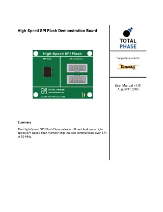
Total Phase High-Speed SPI Flash Demonstration BoardTP280210User manual v1.01 for Total Phase High-Speed SPI Flash Demonstration Board featuring M25P32 32Mbit flash memory with 50MHz SPI interface. Covers connections, powering, cross-connecting adapters, and... |
User Manual | Total Phase | v1.01 | 192 KB |
| User Manual | Total Phase | 360 KB | ||
| Case Study | Total Phase | 600 KB | ||
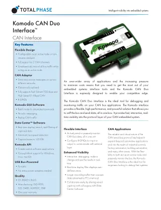
Total Phase Komodo CAN Duo InterfaceTP360110Technical specifications for the Komodo CAN Duo Interface featuring dual CAN channel monitoring, active node functionality, and real-time debugging capabilities. Supports up to 1 Mbps CAN... |
Datasheet | Total Phase | 187 KB | |
| Datasheet | Total Phase | 252 KB | ||
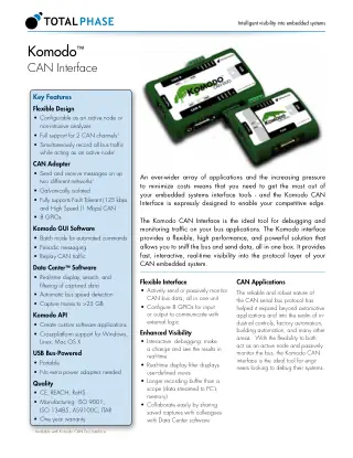
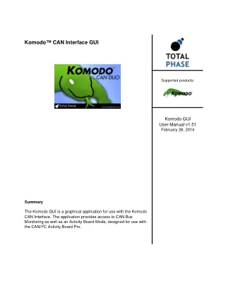
Total Phase Komodo CAN Interface GUITP360110Comprehensive user manual for Total Phase Komodo CAN Interface GUI software v1.51. Covers CAN bus monitoring, data transmission, Activity Board mode, General CAN mode, and batch... |
User Manual | Total Phase | v1.51 | 579 KB |
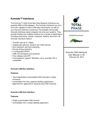
Total Phase Komodo CAN InterfaceTP360110Complete user manual for Total Phase Komodo CAN Duo and Solo interfaces covering installation, configuration, API documentation, and troubleshooting. Version 1.22 includes USB-to-CAN adapter setup, GPIO... |
User Manual | Total Phase | v1.22 | 481 KB |
Total Phase Komodo CAN InterfaceTP360110 |
User Manual | Total Phase | 995 KB | |
Total Phase Komodo GUI SoftwareTP360110 |
User Manual | Total Phase | 1.51 | 775 KB |
Total Phase Level Shifter Board I2C/SPI InterfaceTP240610Comprehensive datasheet for the Total Phase Level Shifter Board v1.00, providing voltage level translation from 1.2V to 3.3V for I2C, SPI, MDIO, and GPIO signals. Compatible... |
Datasheet | Total Phase | 1.00 | 751 KB |
Total Phase Level Shifter Board I2C SPI MDIOTP240610Complete setup and configuration guide for Total Phase Level Shifter Board v1.01. Covers I2C/SPI/MDIO signal level shifting from 1.2V to 3.3V, power options, connector pinouts, and... |
User Manual | Total Phase | 1.01 | 545 KB |
Total Phase Level Shifter BoardTP240610 |
User Manual | Total Phase | 684 KB | |
Total Phase Probing Techniques for Protocol AnalyzersTP320510, TP322610 |
White Paper | Total Phase | v1.00 | 388 KB |
| User Manual | Total Phase | 1.10 | 1.4 MB | |
Total Phase Promira I2C/SPI ActiveTP600110, TP600210, TP600510, TP600610, TP600710 |
User Manual | Total Phase | 1.39 | 1.8 MB |
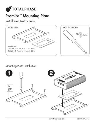
Total Phase Promira Mounting Plate InstallationTP500110Installation instructions for the Total Phase Promira Mounting Plate. Provides dimensions (140mm x 73mm), mounting specifications, and step-by-step installation guidance. Includes adhesive pad for secure platform... |
User Manual | Total Phase | 92 KB | |
| Datasheet | Total Phase | 134 KB | ||
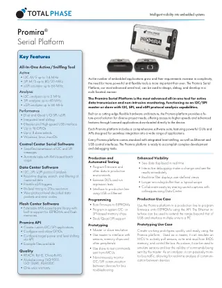
Total Phase Promira Serial PlatformTP500110, TP512110, TP600110, TP600210, TP600510, TP600610, TP600710, TP601010 |
Datasheet | Total Phase | 231 KB | |
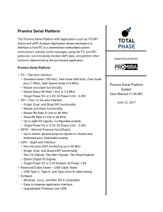
Total Phase Promira Serial Platform I²C, SPI & eSPI InterfaceTP500110This User Manual v1.35.001 provides comprehensive guidance on setup, configuration, and advanced usage of the Promira Serial Platform for I²C, SPI, eSPI, GPIO, and USB cable... |
User Manual | Total Phase | Rev 1.35 | 483 KB |
Total Phase Promira Serial Platform SystemTP500110, TP512110, TP512510 |
User Manual | Total Phase | 1.35 | 776 KB |
| Case Study | Total Phase | 163 KB | ||
| White Paper | Total Phase | 390 KB | ||
| White Paper | Total Phase | 209 KB | ||
| White Paper | Total Phase | 484 KB | ||
| Certificate | Trycom | 52 KB | ||
| « Previous 1 2 3 4 Next » | ||||