
Tag-Connect, LLC
Tag Connect TC2030-CTX-STDC14 Cable
Tag Connect TC2030-CTX-STDC14 Cable
SKU: TC2030-CTX-ST14
Couldn't load pickup availability
Key Features
Overview
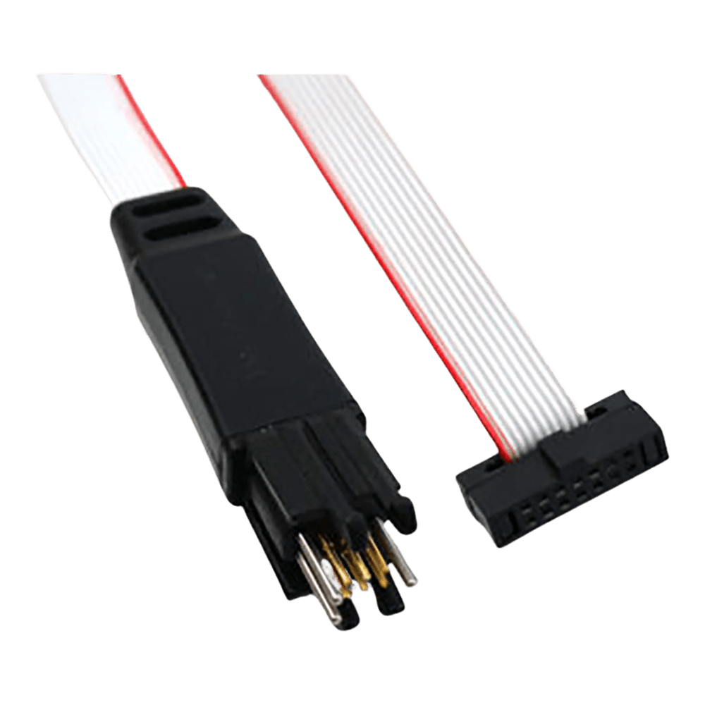
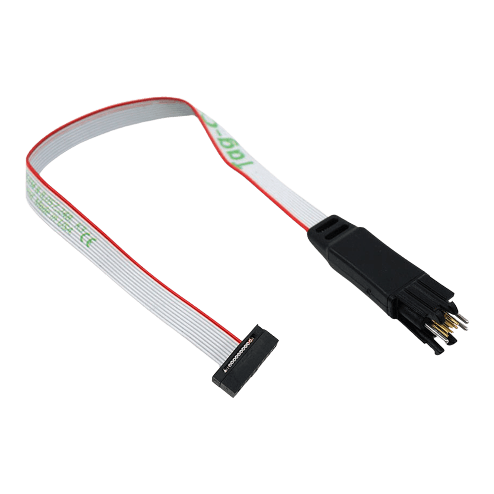
The Tag-Connect TC2030-CTX-STDC14 is a six-pin Plug-of-Nails™ cable that connects a TC2030 Cortex SWD footprint on your PCB directly to the STDC14 (1.27 mm) header used by ST-LINK/V3 debuggers. It carries the essential SWD signals and SWO trace, allowing fast bring-up and programming without fitting a mating connector on the target board.
Choose the legged version here for hands-free use during development. If you prefer a no-legs variant for production, see the TC2030-CTX-NL-STDC14 used with a TC2030-CLIP retainer. For tools that require 10-pin or 20-pin Cortex connectors, consider the TC2050-IDC-050 family or the TC2030-CTX-20 variant.
The TC2030 footprint saves PCB space and BOM cost by eliminating the on-board header, while the spring-pin contact system offers a reliable temporary connection suitable for both lab and production use. This STDC14 cable is ideal for STM32 designs that adopt ST’s 14-pin interface and need a compact SWD access point on the target.
Former name: TC2030-CTX-ST14.
Downloads
Why Engineers Choose The Tag Connect TC2030-CTX-STDC14 Cable
Space saved on target
Fast bring-up & debug
Production-ready workflow
Pinout, footprint and wiring diagram: TC2030-CTX-STDC14 pinout.
The Tag-Connect TC2030-CTX-STDC14 connects an ST STLINK-V3 debugger's 14-pin STDC14 connector to a 6-pad TC2030 footprint on your PCB, for SWD, SWO and reset on STM32 targets with no header fitted. This is the legged version; the no-legs version is the TC2030-CTX-NL-STDC14.
Which cable fits your debugger? See our Tag-Connect cable guide.
| General Information | |
|---|---|
Part Number (SKU) |
TC2030-CTX-ST14
|
Manufacturer |
|
| Physical and Mechanical | |
Weight |
0.1 kg
|
| Other | |
EAN |
5055383665198
|
Questions and Answers
-
What Are the Unique Competitive Advantages of the TC2030-CTX-STDC14 Versus Traditional Headers?
It removes the fitted programming header, saving connector cost and PCB area, and cuts assembly time and a BOM line item. The spring-pin interface gives fast, repeatable connections.
Legs or no legs. This legged cable is Tag-Connect's development version. For production flashing Tag-Connect points to the no-legs TC2030-CTX-NL-STDC14. -
How Does the TC2030-CTX-STDC14 Compare with More Expensive Probe-socket and Fixture Systems?
The TC2030-CTX-STDC14 gives SWD access, including SWO, through a minimal six-pad footprint with no fitted header. It does not carry full JTAG; that needs a 10-pin TC2050 cable.
Compared with probe-socket systems and bespoke bed-of-nails fixtures, a six-pad plug-of-nails needs less fixturing and a smaller keep-out area (our view).
-
Is the Connection Reliable for Manufacturing and Field Servicing?
The spring-pin plug-of-nails gives a firm, repeatable connection, tested by Tag-Connect to well over 100,000 operations.
Production. Tag-Connect recommends this legged version for development and the no-legs TC2030-CTX-NL-STDC14 for production flashing. -
What Signal Integrity Practices Should I Follow When Using the TC2030-CTX-STDC14?
Keep the SWD routes short, reference them to a solid ground plane and avoid stubs. Use the VTARGET line for level sensing, and keep any series resistors or filters in line with your MCU vendor's recommendations. This is general layout advice (our advice), aimed at clean edges and reliable programming at your probe's SWD speeds.
-
What’s Included on the STDC14 Side, and How Are Signals Mapped to the TC2030 Pads?
The STDC14 end is STMicroelectronics' 14-pin 0.05 in (FTSH-107 style) connector, used on the STLINK-V3 and STLINK-V3MINI; its middle ten pins carry the Cortex 10-pin signals. The cable maps SWD and SWO to the six TC2030 contact pads, giving what you need for SWD sessions without a header on your board.
TC2030 pad Signal 1 VCC (voltage sense) 2 SWDIO/TMS 3 nRESET 4 SWCLK/TCK 5 GND 6 SWO/TDO -
What Is the TAG-Connect TC2030-CTX-STDC14 Cable and What Does It Do?
The Tag-Connect TC2030-CTX-STDC14 is a programming and debug cable that connects a TC2030 "plug-of-nails" footprint on your PCB to an STDC14 (2x7, 1.27 mm) interface. It gives SWD access without fitting a header, saving board space and BOM cost.
-
Which Debuggers and Tools Are Compatible with the TC2030-CTX-STDC14?
Tag-Connect lists it for the STLINK-V3, STLINK-V3MINI and STLINK-V3SET. Being passive, it should fit any probe with the same STDC14 header.
Probe Cable STLINK-V3, STLINK-V3MINI, STLINK-V3SET TC2030-CTX-STDC14 (STDC14 header) ST-LINK/V2 20-pin 0.1 in header: use ARM20-CTX with a TC2030-IDC cable If your probe uses a different connector, a passive adapter to STDC14 may solve it (our advice); Tag-Connect also sells an STDC14-to-Cortex-10 ribbon.
-
Does the TC2030-CTX-STDC14 Support Both SWD and Full JTAG?
No. The cable carries SWD signals, including SWO, for STM32 processors with STLINK-V3 and STLINK-V3MINI. The 6-pad TC2030 footprint has no room for full JTAG; Tag-Connect offers 10-pin TC2050 cables for that.
-
How Do I Lay Out the TC2030 Footprint on My PCB for Use with the TC2030-CTX-STDC14?
Place the standard TC2030 six-pad footprint with its three alignment pin holes and, for this legged cable, the four leg latch holes. All seven holes are required.
Rule Detail Signals to route VREF/VTARGET, GND, SWDIO/TMS, SWCLK/TCK, nRESET, SWO/TDO Keep-out area No tracks or vias inside it Clearance No other track within 0.02 in of a pad Solder paste None on the pads Beyond that, keep traces short, add a nearby ground reference and follow your MCU vendor's SWD layout guidance (our advice).
No questions match your search.