


Mikroelektronika d.o.o.
Balancer 5 Click Board™
Balancer 5 Click Board™
SKU: MIKROE-3853
Couldn't load pickup availability


Overview
The Balancer 5 Click Board™ is an intelligent 2-cell Li-Ion battery charger, system power manager, and battery fuel gauge Click Board™.
The Balancer 5 Click Board™ is based on a BQ25887 controller which has some extra features enabling charging without too much hassle. As a system power distributor, it can supply up to 3.3A to a connected battery. By utilizing an externally connected USB power supply, it can charge a 2-cell Li-Ion battery. A dedicated power management IC with optimized smart power control allows very efficient management of the available power.
Downloads
How Does The Balancer 5 Click Board™ Work?
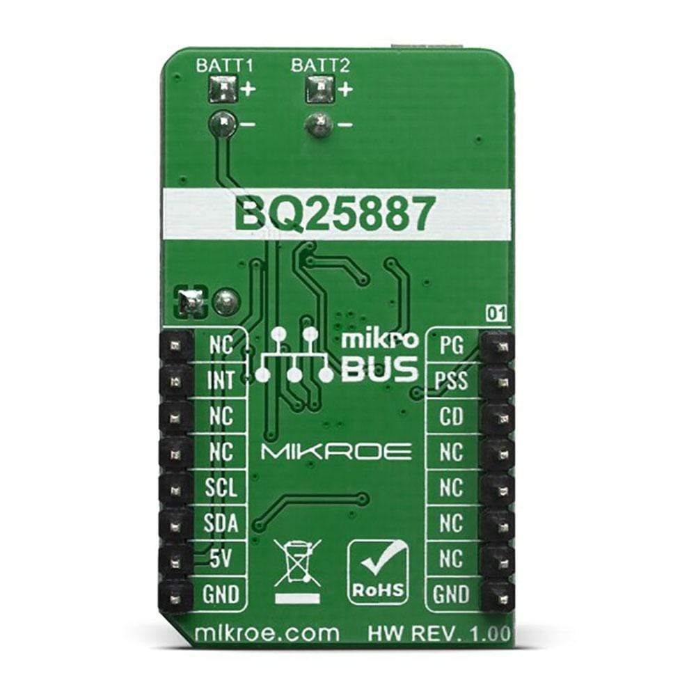
The Balancer 5 Click Board™ is based on the BQ25887 form Texas Instruments- fully integrated 2-cell Li-ion battery charger IC ideal for portable applications with cell balancing. The BQ25887 optimizes the charging two battery with balancing. The input voltage range from USB connector can be as high as 5.5V, battery can be charge with up to 3.3A. When the input voltage exceeds the OVP (Over Voltage Protection) threshold, it will turn off the charging MOSFET to avoid overheating of the chip. Along with its small physical size, the low number of external components makes this IC ideally suitable for various applications.
.jpg)
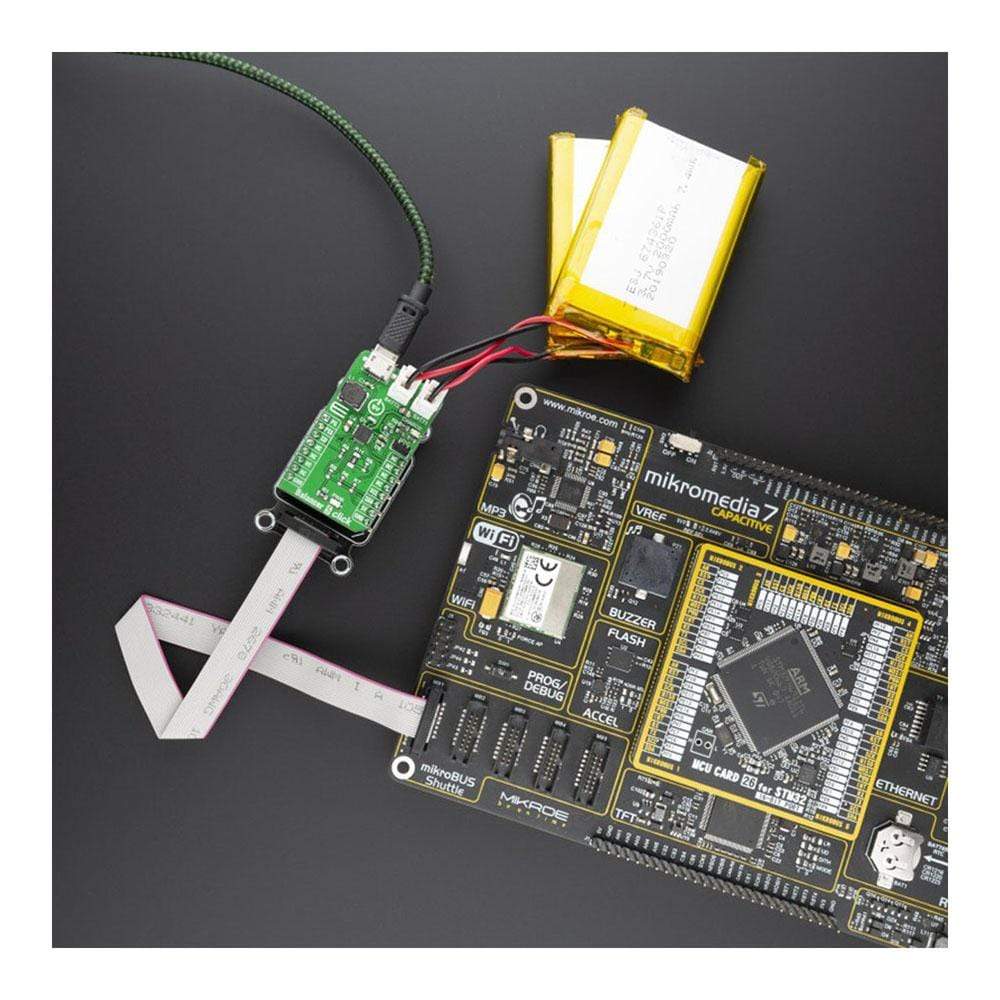
As a Lithium Ion batteries require a very accurate current and voltage for charging, the Balancer 5 Click Board™ can be a perfect solution for such a task. The Balancer 5 Click Board™ is equipped with a highly integrated Li-Ion battery charger, supporting intelligent, constant-current, constant voltage (CCCV), temperature-regulated battery charger charges a 2-cell lithium-ion (Li+) cell batteries. This click has a charging current control IC over I2C interface which ensures perfect and efficient charging. Balancer 5 click can be used as a part of the power supply and distribution system in many applications: different kinds of handheld appliances, portable media players, portable audio players, and other general-purpose battery-operated electronic devices.
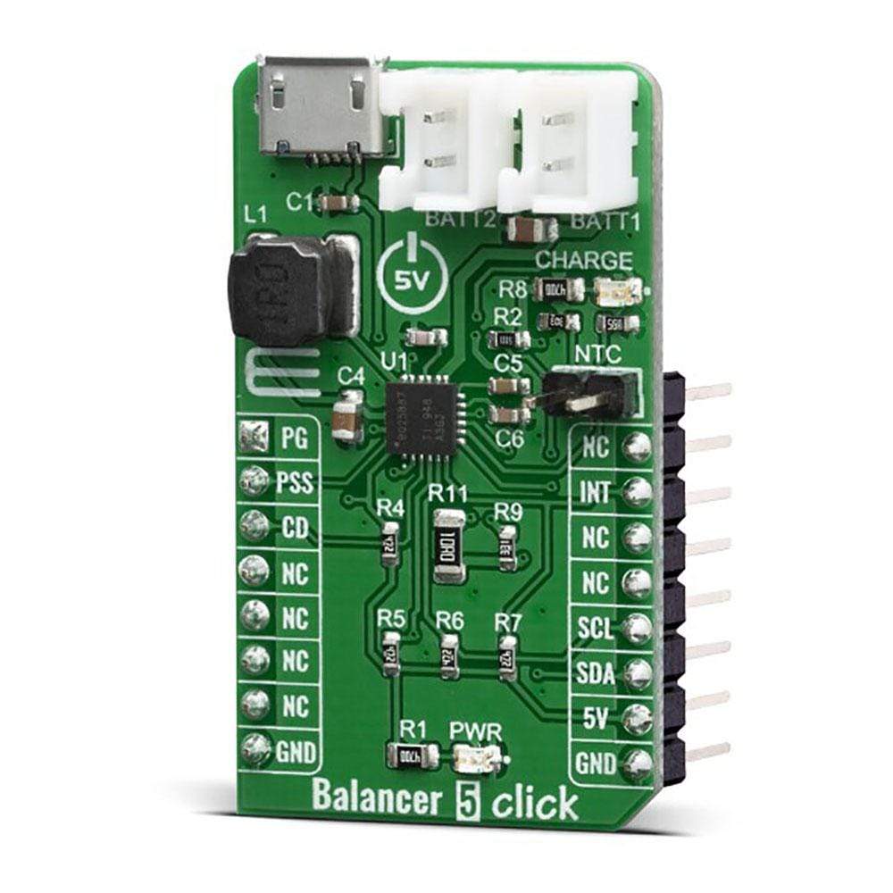
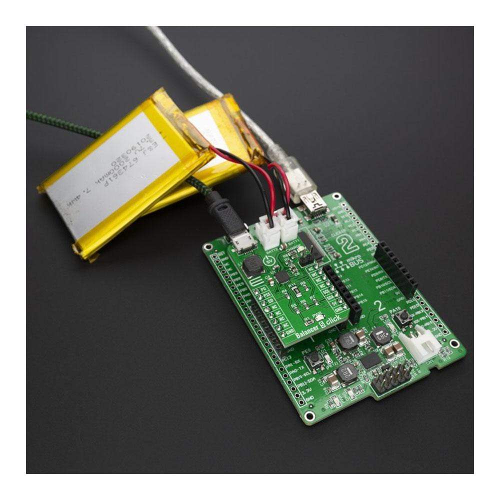
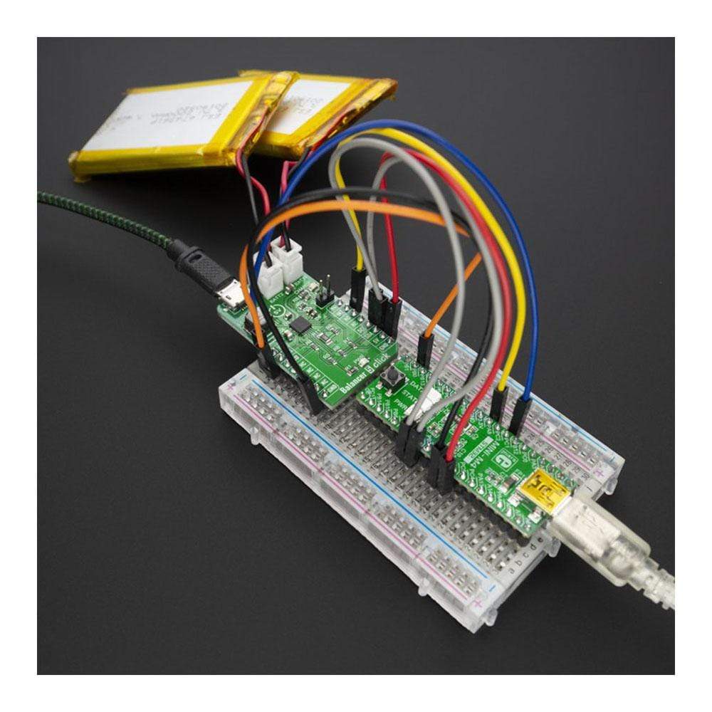
On the left side of the click board is an input USB connector, where the external voltage as high as 5.5V can be applied. Two connectors on the right side is reserved for a Li-Ion batteries with corresponding markings, right connector is for first batteries and left connectr is for secound batteries. When connected to power source, the green CHARGE LED will indicate it, LOW indicates charge in progress. HIGH indicates charge complete or charge disabled. When any fault occurs, the STAT pin blinks at 1Hz. The STAT function can be disabled when the STAT_DIS bit is set.
On right side is 1x2 male header for connect a NTC (Negative temperature Coefficient) resistor. Connect a negative temperature coefficient thermistor. Program temperature window with a resistor divider from REGN to TS to GND. Charge suspends when TS pin is out of range. Recommend 103AT-2 thermistor.
The voltage range which can be used to power up the Balancer 5 click, allows for it to work with 5V capable MCUs.
SPECIFICATIONS
| Type | Battery charger |
| Applications | The Balancer 5 Click Board™ is a perfect choice for development 2S lithium-ion (Li+) cell battery charging with cell balancing. |
| On-board modules | BQ25887, a highly Integrated linear battey charger from Texas Instruments. |
| Key Features | Optimized for USB input and 2-cell Li-Ion, Input current limit to support USB2.0, USB3.0, Battery temperature sensing in charge. |
| Interface | GPIO,I2C |
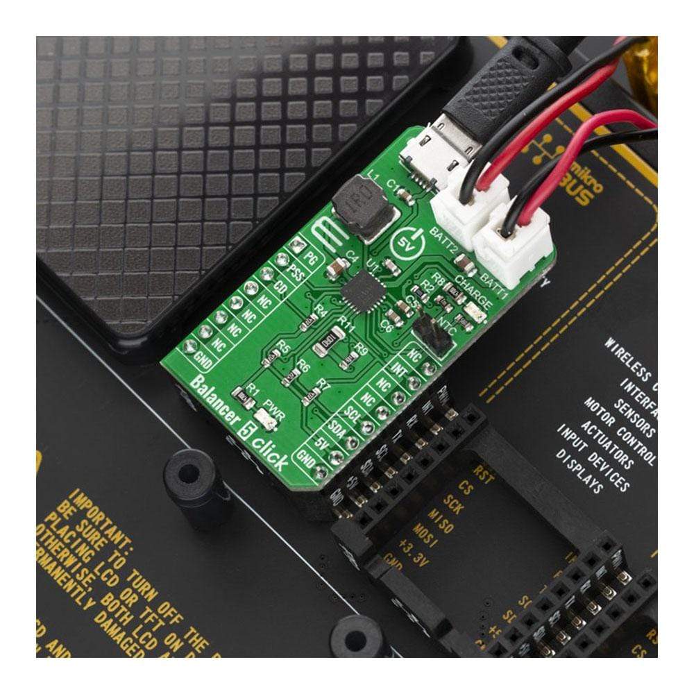
| Compatibility | mikroBUS |
| Click board size | M (42.9 x 25.4 mm) |
| Input Voltage | 5V |
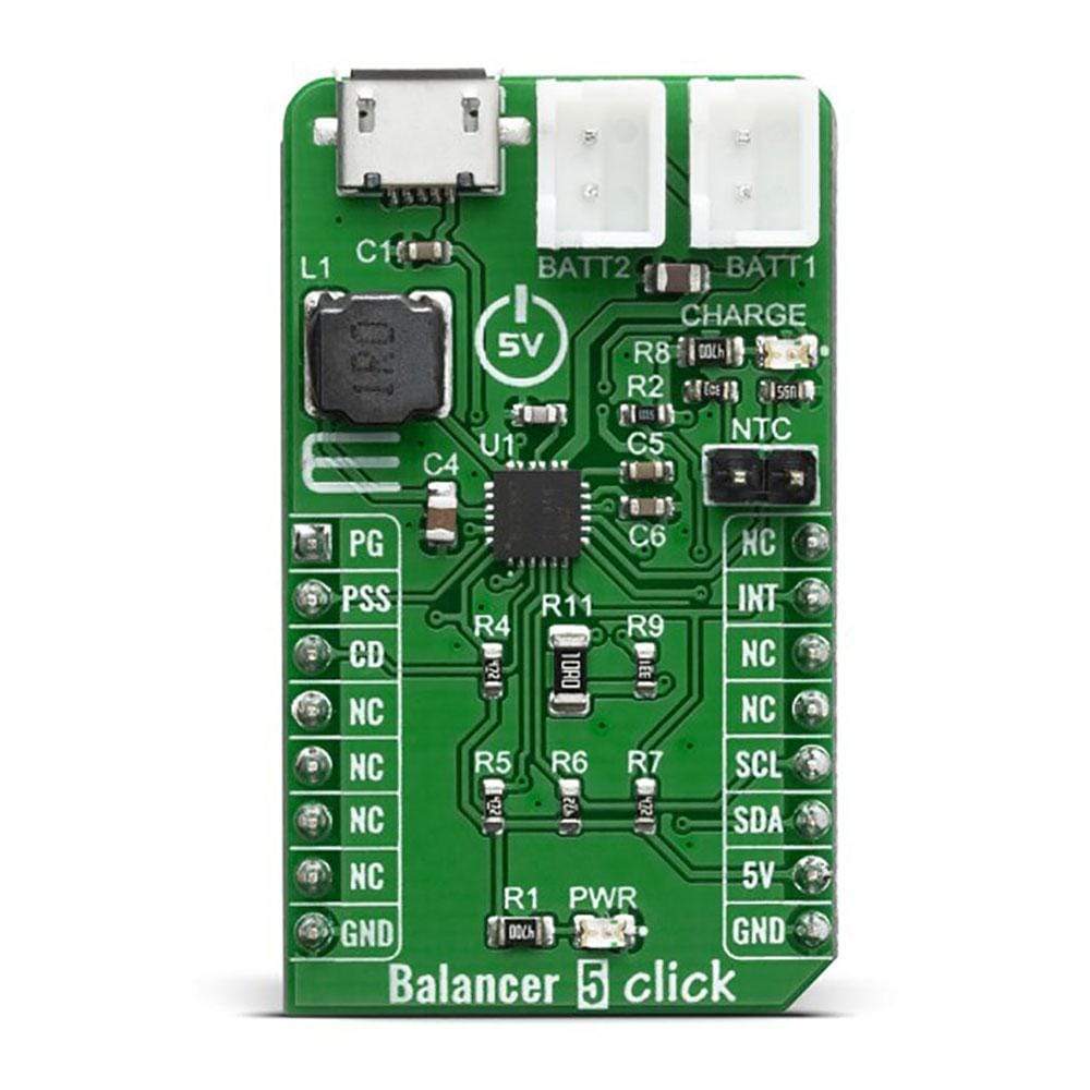
Pinout Diagram
This table shows how the pinout of the Balancer 5 Click Board™ corresponds to the pinout on the mikroBUS™ socket (the latter shown in the two middle columns).
| Notes | Pin | Pin | Notes | ||||
|---|---|---|---|---|---|---|---|
| Power Good | PG | 1 | AN | PWM | 16 | NC | |
| Power Source Selection | PSS | 2 | RST | INT | 15 | INT | Interrupt pin |
| Chip Disable | CD | 3 | CS | RX | 14 | NC | |
| NC | 4 | SCK | TX | 13 | NC | ||
| NC | 5 | MISO | SCL | 12 | SCL | I2C Clock | |
| NC | 6 | MOSI | SDA | 11 | SDA | I2C Data | |
| Power Supply | NC | 7 | 3.3V | 5V | 10 | 5V | Power supply |
| Ground | GND | 8 | GND | GND | 9 | GND | Ground |
ONBOARD SETTINGS AND INDICATORS
| Label | Name | Default | Description |
|---|---|---|---|
| LD1 | PWR | - | Power LED indicator |
| LD2 | STAT | - | Charge status indicator |
| BAT1 | BATT1 | - | Battery connector |
| BAT2 | BATTT2 | - | Battery connector |
| CN1 | USB | - | USB input coltage connector |
| Rt1 | NTC | - | Option battery thermistor connector ( Should be not connect if not used) |
RS485 4 CLICK ELECTRICAL SPECIFICATIONS
| Description | Min | Typ | Max | Unit |
|---|---|---|---|---|
| Input Voltage (at USB CN1 connector) | 3.9 | 5 | 5.5 | V |
| System output voltage (at BATT1 and BATT2 connector) | - | - | 9.2 | V |
| Charging Current (max current selectable by IOUT SEL) | - | 0.5 | 2.2 | A |
| General Information | |
|---|---|
Part Number (SKU) |
MIKROE-3853
|
Manufacturer |
|
| Physical and Mechanical | |
Weight |
0.02 kg
|
| Other | |
EAN |
8606018719495
|
Frequently Asked Questions
Have a Question?
Be the first to ask a question about this.