


Mikroelektronika d.o.o.
AC Current Click Board™
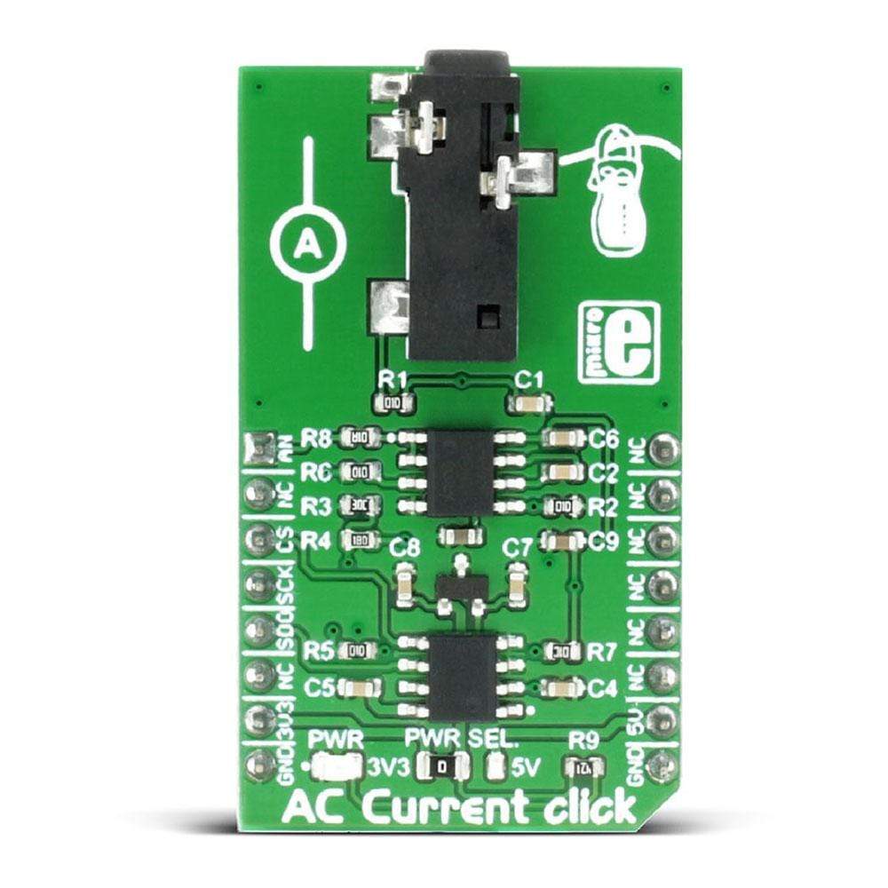
AC Current Click Board™
SKU: MIKROE-2523
Couldn't load pickup availability


Overview
The AC Current Click Board™ can measure alternating currents up to 30A. It features the MCP3201 ADC (analogue to digital) converter and the MCP607 CMOS Op-Amp, both from Microchip. The Click Board™ is designed to run on either a 3.3V or 5V power supply. It communicates with the target MCU over an SPI interface and the AN pin on the MikroBUS™ interface.
The AC Current Click Board™ can only be used for sensors with voltage output (30A input current).
Downloads
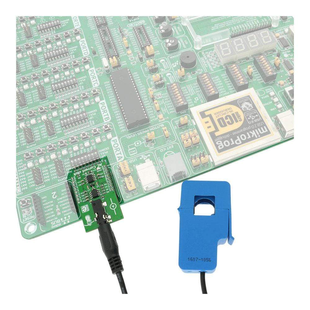
The AC Click Board™ comes equipped with the 3.5mm jack connector which is used to attach the sensing probe. The sensor input is filtered and amplified so that the readings can stay reliable and protected against EMI and radio-interferences. The low-noise 12-bit SAR A/D converter (ADC) converts the sensor voltage, providing conversion data via the industry-standard SPI interface. Besides the onboard A/D converter, there is an analog signal path available to the users, allowing the AC Click Board™ to fit into various usage scenarios. Featuring a high precision ADC and a low noise, rail to rail dual operational amplifier, designed to work with the contactless non-invasive current sensor, the AC Click Board™ is an ideal solution for measuring AC Current through mains and other cables with otherwise dangerous voltages, current consumption monitoring, and similar applications.
How Does The AC Click Board™ Work?
The AC Click Board™ is equipped with the MCP3201, a 12bit SAR analog-to-digital converter (ADC) with SPI interface, from Microchip. The reference voltage for the conversion is 2.048V, and it is provided by the MCP1501, a high-precision, buffered voltage reference IC, also from Microchip. It is used to sample the input voltage, generated by the contactless, non-invasive current sensor, attached to the 3.5mm jack connector.
As already mentioned, the sensor output voltage is a result of the electromagnetic induction of the magnetic field generated by the cable, through which the AC current runs. The split core of the sensor can be clamped over the cable, providing a closed path for the magnetic flux through the core that way. This will result in generating the voltage in the secondary coil within the sensor. This generated voltage depends on the sensor type and the maximum current it is supposed to measure. AC Click Board™ allows measuring up to 10 A / 1 V, using a sensor that outputs 1 V for the full-scale reading of 10 A. Note that only the AC current can be measured, since the DC current does not have the ability to generate the alternating magnetic field, so the sensor can be used only for the AC current measurement.
The voltage at the input is filtered by the RC filter in order to prevent any additional EMI influences or radio-interferences. The signal is then amplified by the MCP607, a rail-to-rail operational amplifier with a very low offset voltage and biasing current. This allows a minimal distortion of the input. The amplification ratio (G) is calculated by using the formula for the non-inverting operational amplifier configuration: G = 1 + R4 / R3. Knowing the maximum voltage of the sensor (for 10A current), the reference voltage of 2.048V for the ADC and the gain factor of the op-amp, it is easy to calculate the value for the measured current. The AC Click Board™ comes with the library functions that do all the necessary calculations, providing a simple and quick solution for the application development. A user can also easily develop his own methods and functions by utilizing the existing ones if some other sensor with different nominal values is used. However, the AC Click Board™ also comes as the part of the AC Current click - bundle, which also contains the current measuring sensor, calibrated and well suited to work with the AC Current click (10A - 1V).
Besides the onboard ADC, it is possible to use an external converter, by using the AN pin of the mikroBUS™. The preconditioned voltage from the first (non-inverting) operational amplifier is routed to both the onboard ADC and another op-amp, which acts as the buffer with unity gain. It is used to provide a buffered analog voltage at the AN pin, which can be used externally, bypassing the onboard ADC. The MCP607 consists of two integrated op-amps so the same IC is used both for the input pre-conditioning and the output buffer.
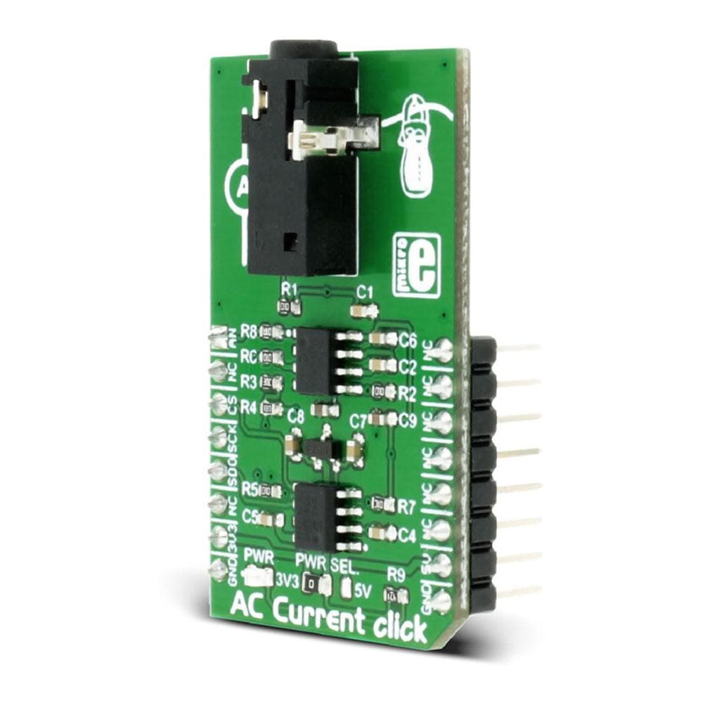
The AC Click Board™ can use both 3.3V and 5V as the power supply, so it is able to directly interface with both 3.3V and 5V MCUs. To select the desired operating voltage, it is enough to switch the onboard SMD jumper, labeled as the PWR SEL.
Please note that the product described on this page does not include the non-invasive current measurement sensor. To get both the AC Click Board™ and the non-invasive current measurement sensor, which is calibrated and well suited for use with the AC current click, please visit the AC Current click - bundle product page for more information and ordering.
Note that although the AC Click Board™ is meant to be used for measuring current without making any contact, by using galvanically isolated sensor over an isolated cable, a special care should always be taken when working with dangerous and harmful voltages. Any operation which involves high voltage should be performed by trained personnel.
SPECIFICATIONS
| Type | Measurements |
| Applications | The AC Click Board™ is an ideal solution for measuring AC Current through mains and other cables with otherwise dangerous voltages, current consumption monitoring, and similar applications |
| On-board modules | MCP3201, a 12bit SAR analog-to-digital converter (ADC) with SPI interface, from Microchip; MCP1501, a high-precision, buffered voltage reference IC, also from Microchip; MCP607, a rail-to-rail CMOS operational amplifier |
| Key Features | Non-invasive, contactless measurement, two types of reading: digital and analog, high resolution onboard ADC converter, low offset and bias current op-amp with input signal RC filtering |
| Interface | Analog,SPI |
| Compatibility | mikroBUS |
| Click board size | M (42.9 x 25.4 mm) |
| Input Voltage | 3.3V or 5V |
PINOUT DIAGRAM
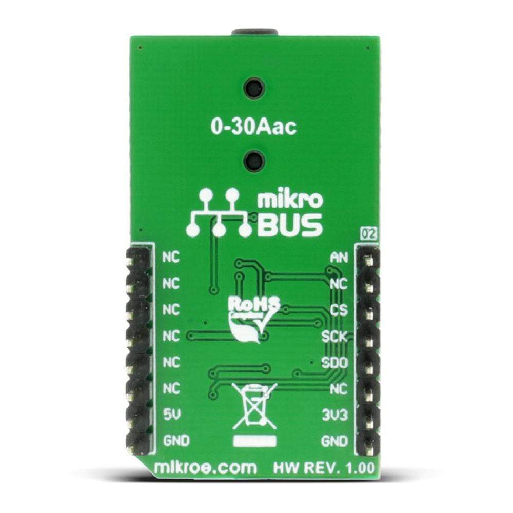
This table shows how the pinout on the AC Click Board™ corresponds to the pinout on the mikroBUS™ socket (the latter shown in the two middle columns).
| Notes | Pin | Pin | Notes | ||||
|---|---|---|---|---|---|---|---|
| Analog OUT | AN | 1 | AN | PWM | 16 | NC | |
| NC | 2 | RST | INT | 15 | NC | ||
| SPI Chip select | CS | 3 | CS | TX | 14 | NC | |
| SPI Clock | SCK | 4 | SCK | RX | 13 | NC | |
| Serial data OUT | MISO | 5 | MISO | SCL | 12 | NC | |
| NC | 6 | MOSI | SDA | 11 | NC | ||
| Power supply | +3.3V | 7 | 3.3V | 5V | 10 | +5V | Power supply |
| Ground | GND | 8 | GND | GND | 9 | GND | Ground |
ONBOARD JUMPERS AND SETTINGS
The table below shows information about onboard jumpers:
| Designator | Name | Default | Description |
|---|---|---|---|
| LD1 | PWR | - | Power LED indicator |
| JP1 | PWR SEL | Left | Power Supply Voltage Selection 3.3V/5V, left position 3.3V, right position 5V |
| General Information | |
|---|---|
Part Number (SKU) |
MIKROE-2523
|
Manufacturer |
|
| Physical and Mechanical | |
Weight |
0.019 kg
|
| Other | |
EAN |
8606015079967
|
Frequently Asked Questions
Have a Question?
Be the first to ask a question about this.