


Mikroelektronika d.o.o.
LCD Mono Click Board™
LCD Mono Click Board™
SKU: MIKROE-3789
Couldn't load pickup availability


Overview
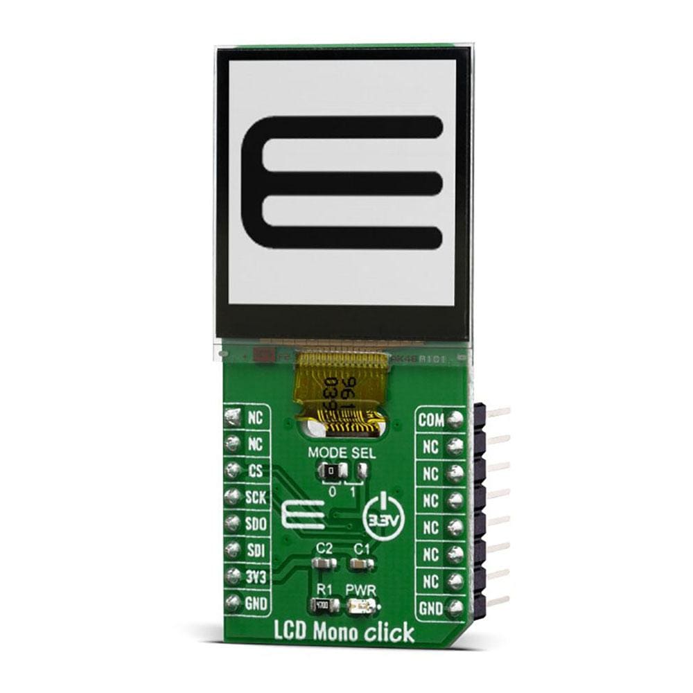
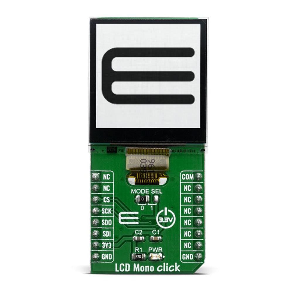
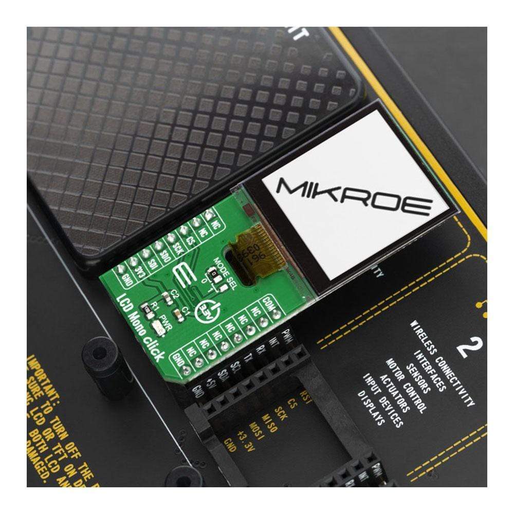
The LCD Mono Click Board™ uses the LS013B7DH03 LCD display from Sharp which combined with the EFM32, from Silicon Labs, and its energy-saving capabilities create a powerful display application. The application is capable of driving a 128x128 pixel display drawing as little as 2 µA while showing a static image. Even when updating the frame every second the current consumption can be lower than 5 µA.
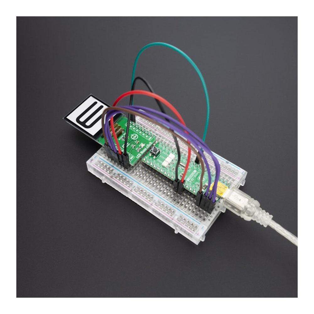
LCD Mono Click is supported by a mikroSDK compliant library, which includes functions that simplify software development. This Click Board™ comes as a fully tested product, ready to be used on a system equipped with the mikroBUS™ socket.
Downloads
How Does The LCD Mono Click Board™ Work?
The LS013B7DH03 LCD display from Sharp has a reflective active-matrix with slightly transmissive type memory liquid crystal display module with 128 x128 panel which uses CG silicon thin film transistor. Its transmissive mode is available by implementation with backlight and you can control the display with serial data signal communication. It features a thin, light and compact module with monolithic technology and its most important feature is the super low power consumption TFT panel. For an MCU application, a powerful display can often be off-limits, either because of price, CPU processing power or power budget. However, if you use the EFM32's energy saving capabilities together with a Sharp low-power matrix memory LCD you can create a powerful display application. The application is capable of driving a 128x128 pixel display drawing as little as 2 µA while showing a static image. Even when updating the frame every second the current consumption can be lower than 5 µA.
The display used for the LCD Mono Click Board™, the LS013B7DH03 LCD, is a 1.28", 128x128 pixels monochrome display, with a 3-wire SPI interface. Apart from the SPI interface, the display requires a 3.3V power supply, and 3 extra pins named EXTMODE, EXTCOMIN and DISP. The SPI protocol consists of three modes. At the start of each SPI transfer, a mode command (1 byte) is sent first. The modes are:
- Update Image
- Toggle Polarity Inversion
- Clear Display
The EXTMODE pin controls how polarity inversion is controlled. The display requires that the polarity across the Liquid Crystal Cell is reversed at a constant frequency. This polarity inversion prevents charge building up within the cell. If EXTMODE is LOW the polarity inversion is toggled by sending a special command over SPI. If it is HIGH polarity inversion is controlled by the EXTCOMIN pin. If EXTMODE is HIGH the polarity inversion is armed for every rising edge of the EXTCOMIN pin. The actual polarity inversion is triggered at the next transision of SCS. The toggling frequency should be at least 1 Hz. If EXTMODE is LOW this pin is ignored. The DISP pin toggles the display on or off (without the pixels losing their state). When LOW the display is off, when HIGH the display is on.
The LCD Mono Click Board™ is designed to be operated only with 3.3V logic level. A proper logic voltage level conversion should be performed before the LCD Mono Click Board™ is used with MCUs with logic levels of 5V.
SPECIFICATIONS
| Type | LCD |
| Applications | 128x128 pixels monochrome display, with a 3-wire SPI interface |
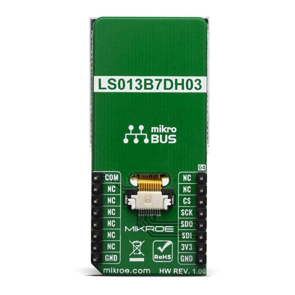
| On-board modules | LS013B7DH03 LCD display from Sharp |
| Key Features | EFM32 helps reduce power consumption, driving a 128x128 pixel display drawing as little as 2 µA while showing a static image |
| Interface | GPIO,SPI |
| Compatibility | mikroBUS |
| Click board size | L (57.15 x 25.4 mm) |
| Input Voltage | 3.3V |
PINOUT DIAGRAM
This table shows how the pinout on the LCD Mono Click Board™ corresponds to the pinout on the mikroBUS™ socket (the latter shown in the two middle columns).
| Notes | Pin | Pin | Notes | ||||
|---|---|---|---|---|---|---|---|
| NC | 1 | AN | PWM | 16 | COM | COM Inversion polarity OUT | |
| NC | 2 | RST | INT | 15 | NC | ||
| Chip Enable | CS | 3 | CS | RX | 14 | NC | |
| SPI Clock | SCK | 4 | SCK | TX | 13 | NC | |
| SPI Data Out | SDO | 5 | MISO | SCL | 12 | NC | |
| SPI Data IN | SDI | 6 | MOSI | SDA | 11 | NC | |
| Power Supply | 3.3V | 7 | 3.3V | 5V | 10 | NC | |
| Ground | GND | 8 | GND | GND | 9 | GND | Ground |
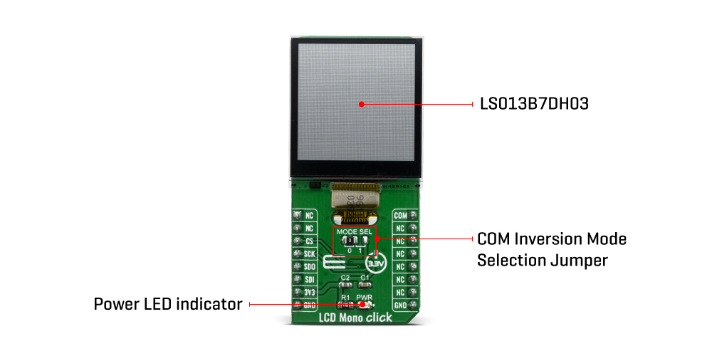
ONBOARD SETTINGS AND INDICATORS
| Label | Name | Default | Description |
|---|---|---|---|
| LD1 | PWR | - | Power LED indicator |
| JP1 | MODE SEL | Left | COM Inversion mode Selection jumper: left position 0, right position 1 |
| General Information | |
|---|---|
Part Number (SKU) |
MIKROE-3789
|
Manufacturer |
|
| Physical and Mechanical | |
Weight |
0.02 kg
|
| Other | |
EAN |
8606018719877
|
Frequently Asked Questions
Have a Question?
Be the first to ask a question about this.