Overview
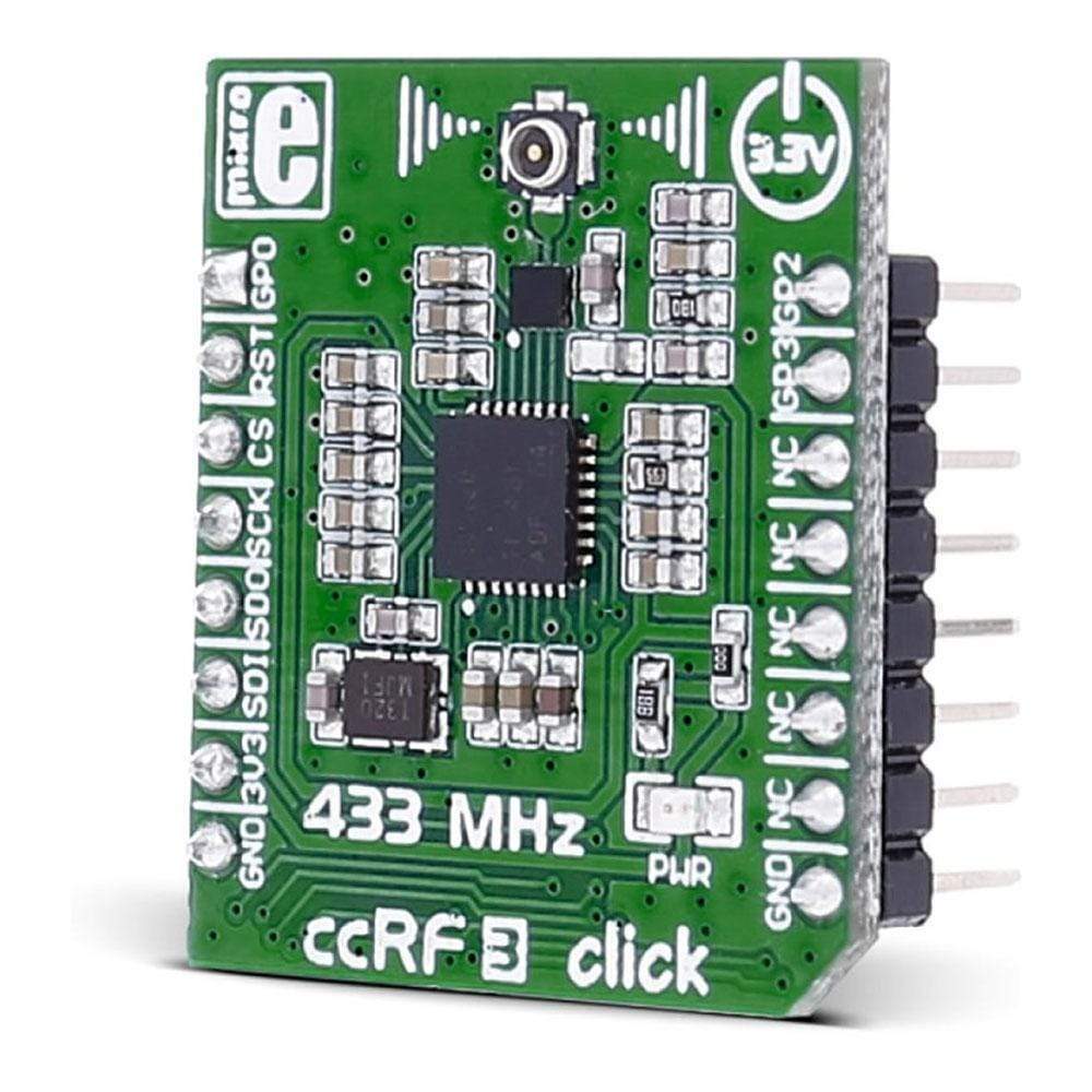
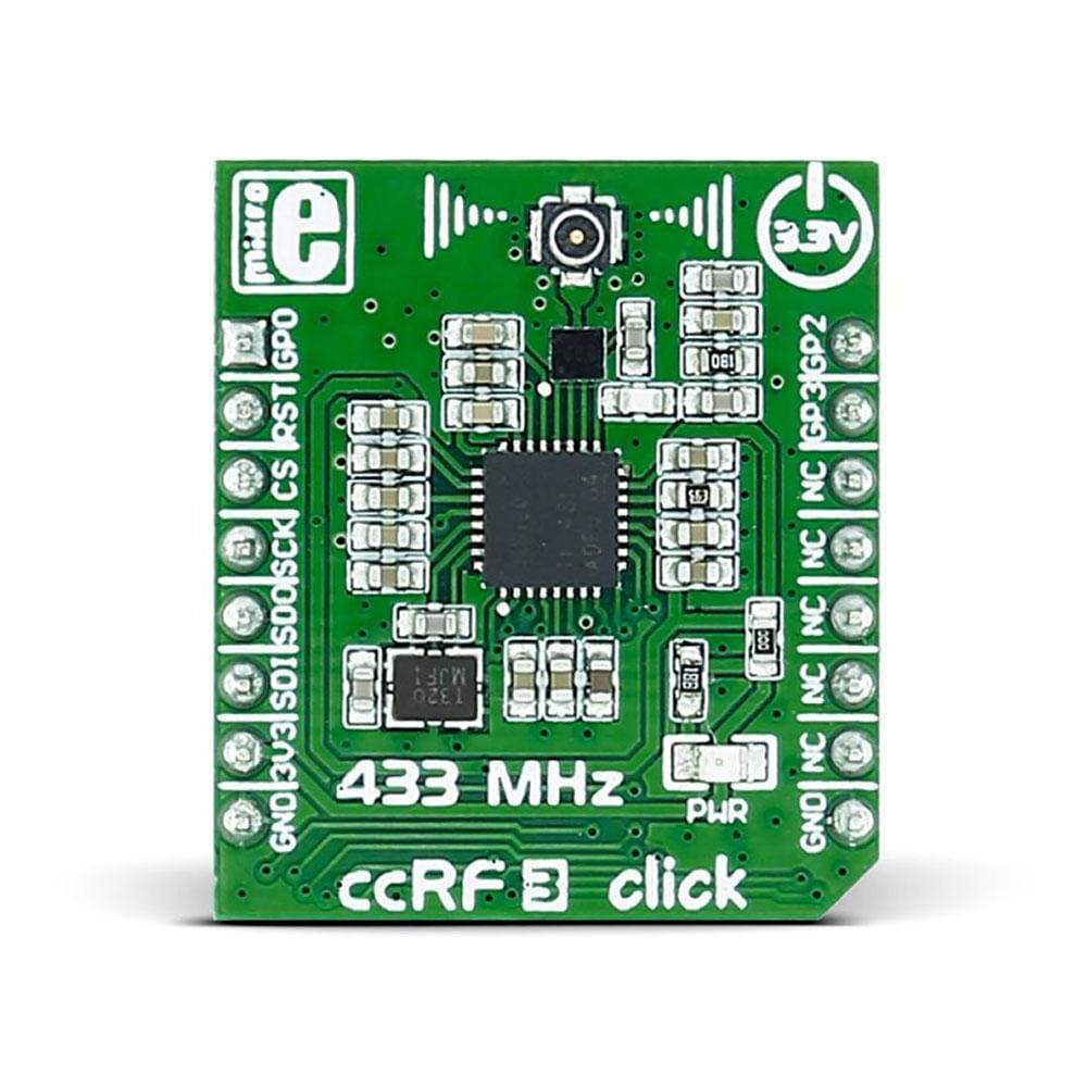
The ccRF 3 Click Board™ carries the CC1120 high-performance RF transceiver for narrowband systems from Texas Instruments.
The Click Board™ will enable you to add a low-power consumption radio transceiver at 433 MHz frequency. The ccRF 3 Click Board™ is designed to run on a 3.3V power supply. It communicates with the target microcontroller via an SPI interface.
Downloads
The ccRF 3 Click Board™ carries the CC1120 high-performance RF transceiver for narrowband systems from Texas Instruments. The clicks will enable you to add a low-power consumption radio transceiver at 433 MHz frequency . ccRF 3 click is designed to run on a 3.3V power supply. It communicates with the target microcontroller over SPI interface, with additional functionality provided by the following pins on the mikroBUS™ line: AN, RST, CS, PWM, INT.
Note : the click requires an external N.FL. antenna
CC1120 RF TRANSCEIVER FEATURES
| The CC1120 device is a fully integrated single-chip radio transceiver designed for high performance at very low-power and low-voltage operation. | 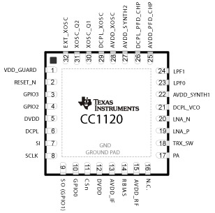 |
The device is mainly intended for Industrial, Scientific, and Medical (ISM) applications and Short Range Device (SRD). |
The CC1120 device provides extensive hardware support for packet handling, data buffering, burst transmissions, clear channel assessment, link quality indication, and wake-on-radio. The main operating parameters of the CC1120 device can be controlled through an SPI interface.
WAKE-ON-RADIO
Wake-On-Radio or eWOR y enables CC1120 to periodically wake up from SLEEP and listen for incoming packets without MCU interaction.
When the CC1120 device enters RX mode, it listens and then returns to sleep if a valid RF packet is not received. The sleep interval and duty cycle can be configured to make a trade-off between network latency and power consumption. Incoming messages are time-stamped to simplify timer resynchronization. The eWOR timer runs off an ultra-low-power 32-kHz RC oscillator.
Power Consumption
In IDLE mode the CC1120 uses 1.3mA, while in power down with retention mode the consumption goes to 0.12µA.
SMARTRF™ Studio Software
CC1120 can be configured using the SmartRF™ Studio software. SmartRF™ Studio is highly recommended for obtaining optimum register settings, and for evaluating performance and functionality.
After chip reset, all registers have default values and these might differ from the optimum register setting. It is therefore necessary to configure/reconfigure the radio through the SPI interface after the chip has been reset. SmartRF Studio provides a code export function making it easy to implement this in firmware.
SPECIFICATIONS
| Type | ccRF,Sub-1 GHz Transceievers |
| Applications | Narrowband ultra-low-power wireless systems with channel spacing down to 12.5 kHz, wireless metering and wireless smart grid, home and building automation, wireless alarm and security sytems, etc. |
| On-board modules | CC1120 high-performance RF transceiver for narrowband systems |
| Key Features | Power consumption of 1.3mA in IDLE mode, 433 MHz frequency band |
| Interface | GPIO,SPI |
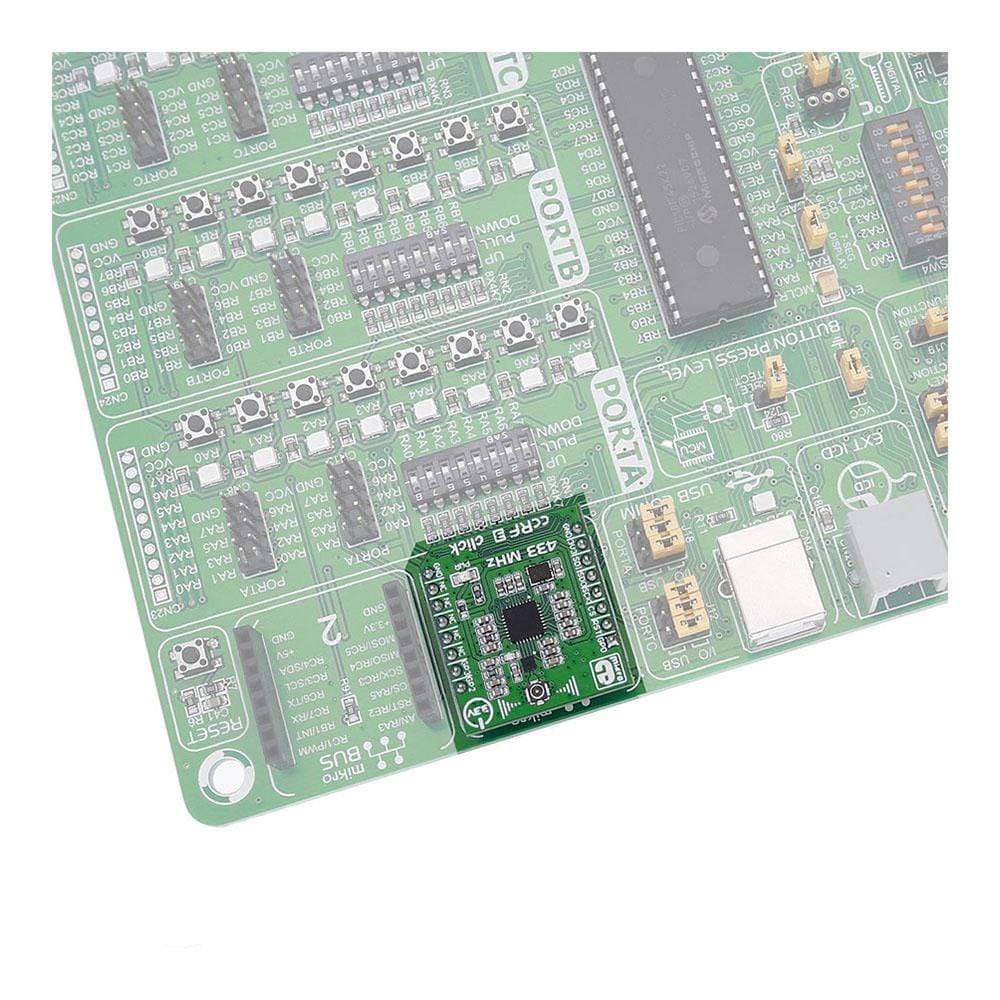
| Compatibility | mikroBUS |
| Click board size | S (28.6 x 25.4 mm) |
| Input Voltage | 3.3V |
PINOUT DIAGRAM
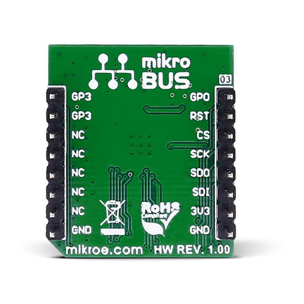
This table shows how the pinout on the ccRF 3 Click Board™ corresponds to the pinout on the mikroBUS™ socket (the latter shown in the two middle columns).
| Notes | Pin |  |
Pin | Notes | |||
|---|---|---|---|---|---|---|---|
| GPIO0 | GP0 | 1 | AN | PWM | 16 | GP2 | GPIO2 |
| Reset | RST | 2 | RST | INT | 15 | GP3 | GPIO3 |
| SPI Chip Select | CS | 3 | CS | TX | 14 | NC | |
| SPI Clock Pin | SCK | 4 | SCK | RX | 13 | NC | |
| SPI master in slave out pin for the MCU | MISO | 5 | MISO | SCL | 12 | NC | |
| SPI master out slave in pin for the MCU | MOSI | 6 | MOSI | SDA | 11 | NC | |
| Power supply | +3.3V | 7 | 3.3V | 5V | 10 | NC | |
| Ground | GND | 8 | GND | GND | 9 | GND | Ground |
| General Information | |
|---|---|
Part Number (SKU) |
MIKROE-2389
|
Manufacturer |
|
| Physical and Mechanical | |
Weight |
0.018 kg
|
| Other | |
Country of Origin |
|
HS Code Customs Tariff code
|
|
EAN |
8606015079127
|
Warranty |
|
Frequently Asked Questions
Have a Question?
Be the first to ask a question about this.

