


Tag-Connect, LLC
Tag Connect TC2070-IDC-050 14-Pin Programming Cable
Tag Connect TC2070-IDC-050 14-Pin Programming Cable
SKU: TC2070-IDC-050
Couldn't load pickup availability
Key Features
Overview
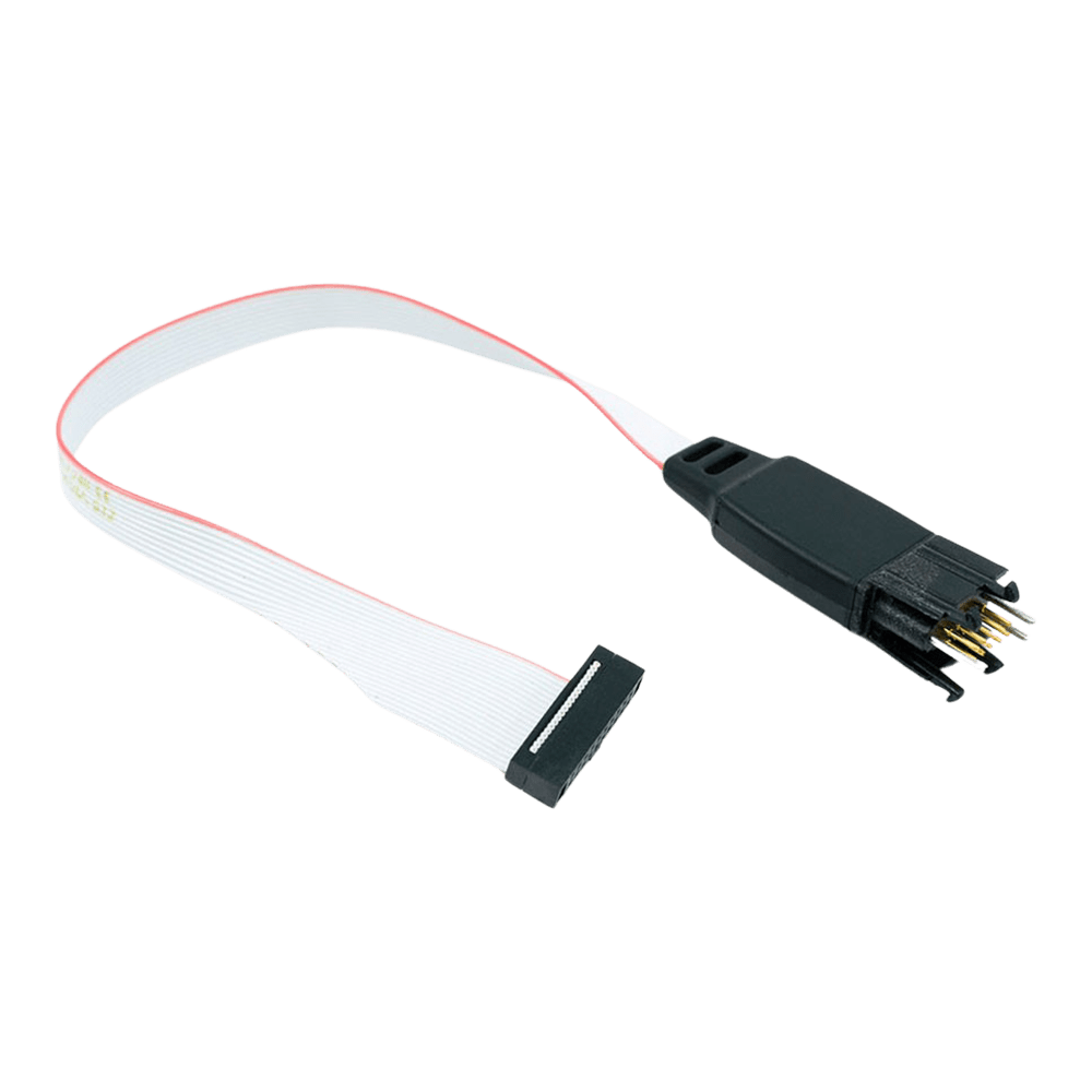
The TC2070-IDC-050 represents Tag-Connect's development-focused approach to microcontroller programming and debugging. This legged variant incorporates four plastic retention clips that lock securely onto the PCB, enabling extended debugging sessions without manual cable support. The 0.05" pitch IDC termination ensures compatibility with modern debuggers including ST-LINK V3, ST-LINK V3MINI, and other STDC14-compatible tools.
Ideal for bench development where sustained connections are essential for setting breakpoints, single-stepping code, and interactive debugging. The retention system maintains reliable electrical contact during board movement or vibration. For production programming applications where brief connections suffice, consider the TC2070-IDC-NL-050 no-legs version which offers a smaller PCB footprint.
Compatible with MSP430, STM32, and other 14-pin JTAG/SWD applications. Retention legs provide mechanical stability for development environments whilst maintaining professional electrical specifications.
Downloads
Why Engineers Choose The Tag Connect TC2070-IDC-050 14-Pin Programming Cable
Hands-Free Development
Professional Reliability
Extended Session Capability
Development-Ready Programming Solution
The TC2070-IDC-050 combines professional microcontroller programming capabilities with hands-free debugging convenience through its integrated retention system. This legged version features four plastic clips that securely lock onto the PCB, enabling sustained development sessions without manual cable holding.
Key Connection Points
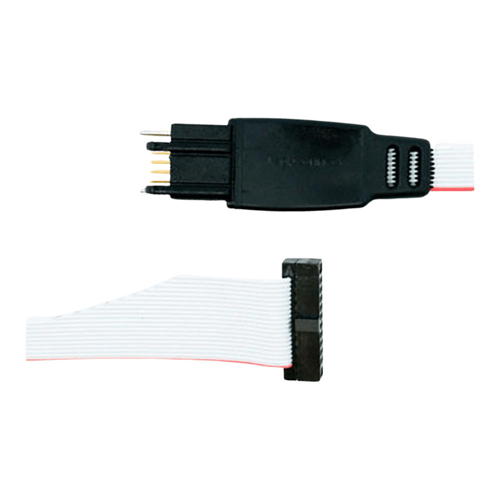
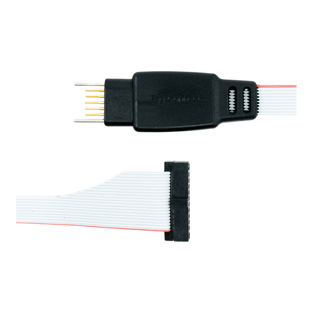
14-pin "Plug-of-Nails" spring-pin connector with plastic retention legs on the PCB end, whilst the debugger end terminates in a 0.05" pitch (1.27mm) female IDC connector for modern STDC14-compatible programmers.
PCB Footprint & Retention System
Requires gold-plated test pads, three alignment holes, plus four additional mounting holes for the plastic retention legs. The complete TC2070 footprint measures approximately 16.5mm x 11.1mm including leg clearance areas, providing secure attachment during extended debugging sessions.
| Parameter | Specification |
|---|---|
| PCB End | 14-pin spring contacts (with legs) |
| Debugger End | 0.05" pitch female IDC |
| Cable Length | Approximately 200mm (8") |
| Contact Rating | 100,000+ operations |
| Retention System | 4 plastic clips + 3 alignment pins |
Wiring Quick-Start
STDC14 Pin TC2070 Pin Signal -----------+-----------+-------- 3 1 VCC 4 2 SWDIO/TMS 5 3 GND 6 4 SWCLK/TCK 7 5 GND 8 6 SWO/TDO 9 7 KEY (NC) 10 8 TDI 11 9 GND Reset 12 10 Reset 13 11 N/C 14 12 N/C 1 13 N/C 2 14 N/C Development Advantage: Retention legs enable hands-free debugging, breakpoint setting, and code stepping without holding the cable manually.
Which cable fits your debugger? See our Tag-Connect cable guide.
| General Information | |
|---|---|
Part Number (SKU) |
TC2070-IDC-050
|
Manufacturer |
|
| Physical and Mechanical | |
Weight |
0.1 kg
|
| Other | |
EAN |
5055383665501
|
Questions and Answers
-
Are the Plastic Retention Legs Replaceable If Damaged?
No, Tag-Connect does not offer replacement legs; the legs are part of the moulded housing. Use the squeeze-to-insert and squeeze-to-remove method Tag-Connect describes to avoid stressing them.
-
Can I Remove the Cable Whilst Power Is Applied to the Target?
Stop the debug session before removing the cable. To remove it, squeeze the side tabs on the connector and lift it straight off the board.
-
What Signals Are Available Beyond Basic SWD Debugging?
The 14-pin STDC14 interface carries JTAG/SWD plus the UART TX and RX lines. Consult your debugger's STDC14 pinout for the full mapping.
-
How Do I Release the Retention Legs From the PCB?
Squeeze the two side tabs on the connector housing, grip it close to the PCB and pull it straight out. Do not lever it off the board.
-
Is This Cable Suitable for Automated Test Equipment Integration?
It suits semi-automated testing where a stable connection is needed. Automated test fixtures usually work better with the faster-cycling no-legs version and a custom retention method.
-
What Is the Difference Between This Part (TC2070-IDC-050) and TC2070-IDC?
Both use the same TC2070 legged plug at the PCB end and fit the same TC2070 footprint; the difference is the pitch of the IDC connector at the tool end.
TC2070-IDC-050 (this cable) <a href='/products/tag-connect-tc2070-idc-cable-uk'>TC2070-IDC</a> Tool-end connector 14-pin (2x7) 0.05″ (1.27 mm) female IDC 14-pin (2x7) 0.1″ (2.54 mm) female IDC Listed solutions ST-LINK-V3SET, ST-LINK-V3, ST-LINK-V3MINI (STDC14 style) PEmicro Multilink Universal/FX, PEmicro Cyclone LC/FX Universal, TI MSP-FET430 PCB end Legged plug Legged plug Footprint TC2070 footprint TC2070 footprint Pick the one that matches your debugger's connector.
-
What Advantages Do the Retention Legs Provide Over the No-legs Version?
The legs hold the cable in place, so you don't have to hold it by hand while setting breakpoints, single-stepping code or doing extended analysis.
-
How Do I Install the Retention Legs Correctly on My PCB?
1Position the connector over the footprint.2Align the three guide pins.3Squeeze the two sides and press gently until the four plastic legs click into their holes.Tag-Connect warns against using excessive force when inserting the connector. -
Can I Use This Cable for Production Programming Applications?
Yes, but the legged version is optimised for development. For production programming, where brief connections are enough, Tag-Connect points to the no-legs version, which has a smaller PCB footprint; as advice, it is also quicker to connect and disconnect.
-
What Debuggers Are Compatible with the 0.05" Pitch IDC Connector?
Debuggers with STDC14 (0.05″ pitch) connectors, such as ST-LINK V3, ST-LINK V3SET and ST-LINK V3MINI. For debuggers with a 14-pin 0.1″ header, choose the TC2070-IDC instead.
-
How Does the PCB Footprint Differ From the No-legs Version?
The legged version needs extra holes in the PCB for its retention legs, so its footprint is larger. The no-legs version needs only the contact pads and locating holes.
Legged (this cable) No legs Contact pads 14 pads, 0.031″ diameter 14 pads Alignment holes 3, 0.039″ diameter 3 Leg latch holes 4, 0.0935″ diameter None Exact dimensions are in Tag-Connect's footprint drawings.

No questions match your search.