


Acute Technology, Inc
Acute BusFinder BF7264 Pro Protocol Analyser
Acute BusFinder BF7264 Pro Protocol Analyser
SKU: BF7264Pro-Base
£11,500.00 exc VAT
Suggested Add-Ons
Optional. Tick any you need. One of each is added to your cart with this item, whatever the quantity.
Check and Add to Cart
Confirm the price and stock for your selection, set the quantity, then press Add to Cart.
Metodi di pagamento
- Bank transfer
Impossibile caricare la disponibilità di ritiro


Caratteristiche principali
Overview
The Acute BusFinder BF7264 Pro is a modular 2‑in‑1 instrument combining hardware protocol decoding with a 64‑channel logic analyser, enabling real‑time viewing, deep logging and long‑duration monitoring across storage and high‑speed interfaces.
A 32Gb protocol memory, transitional storage and SSD logging let engineers capture intermittent, system‑level issues that rarely reproduce during short bench sessions.
Protocol options cover eMMC 5.1, SD/SDIO 3.0, SD 4.1 UHS‑II, NAND (ONFI/Toggle), MIPI D‑PHY 1.2, UFS 2.1 and SGMII using dedicated active probes for signal‑integrity‑friendly connections.
Used as a logic analyser, BusFinder overlays bus decodes on waveforms and can be stacked with a DSO for MSO workflows in complex validation tasks.
Download
Datasheets
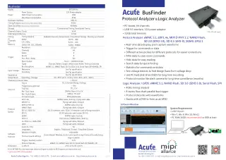 Acute BusFinder 7264 Pro (64-Channel Protocol Analyzer & Logic Analyzer)Acute BusFinder 7264 Pro v2024.03: 64-channel protocol analyzer & logic analyzer with 4GHz timing analysis, 32Gb memory. Supports eMMC 5.1,...
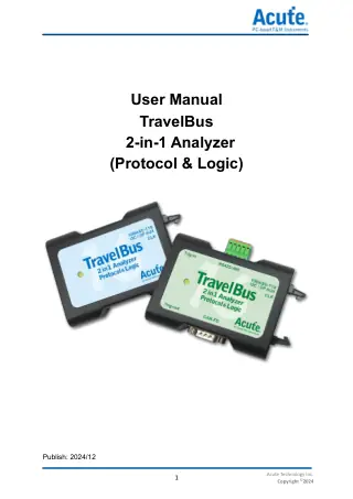 Acute TravelBus 2-in-1 Analyzer (Protocol and Logic Analyzer)Acute TravelBus 2-in-1 Protocol & Logic Analyzer user manual (2024/12 version). Features 16 channels, USB 3.0 interface, supports multiple protocols...
User Manuals
- Details
 Acute Bus/Trigger Decoder ManualAcute DeTrig Series Bus/Trigger Decoder User Manual, Version 2018. Comprehensive guide covering supported bus types and trigger functions.
Perché gli ingegneri scelgono Acute BusFinder BF7264 Pro Protocol Analyser
Months‑long capture
One box, many buses
Correlated insights
The Acute BusFinder BF7264 Pro protocol analyser is a PC-based, 64-channel instrument with 32 Gb of memory and a USB 3.0 link, built for analysing storage and high-speed serial buses. Fitted with the matching protocol option it analyses eMMC 5.1, UFS 2.1, MIPI D-PHY 1.2, eDP 1.4a, SD 3.0 (SDIO 3.0), SD 4.1 (UHS-II), ONFI and Toggle NAND, SGMII and LTPI in hardware, and it also works as a logic analyser with up to 4 GHz timing (with the optional LA4G-POD). It suits storage, MIPI D-PHY and eDP debug and long-run failure capture.
Hardware Protocol Analysis for eMMC, UFS and MIPI D-PHY
Each protocol option is a dedicated active probe kit for one bus. The eMMC option covers HS400, HS200 and Command Queue. MIPI D-PHY runs up to 2.0 Gbps per lane on 1 clock plus 4 data lanes, eDP 1.4a up to 5.4 Gbps per lane on 4 lanes, and SD 4.1 (UHS-II) up to 1.56 Gbps per lane. NAND covers ONFI 4.1 (NV-DDR3) Mode 8 and Toggle DDR 2.0 (~267 MHz).
The analyser decodes in hardware and shows commands and data in real time, with waveforms after capture. Trigger on a command or data value, filter out commands you don't need in hardware before they are stored (every protocol option except LTPI), then search and count commands in the software.
Three Ways to Record a Protocol Analyser Session
Protocol Analyzer shows the data live. Protocol Logger streams it to the PC's SSD. Protocol Monitor records into the instrument's own memory, and Acute rates it for surveillance lasting months.
64-Channel Logic Analyser Mode
Fit an LA-POD 2 (32 channels) or LA4G-POD (16 channels) and the same mainframe becomes a logic analyser as well. It triggers on and decodes eMMC 5.1, NAND flash, SD 3.0 (SDIO 3.0), serial flash (SPI NAND) and SPI with waveforms, and adds the everyday embedded buses from a decode list of more than 100 protocols. Timing runs at 1 GHz on all 64 channels, 2.4 or 2 GHz on 32, and 4 GHz on 16 with the LA4G-POD. The trigger uses 8 states, 8 events and a pass counter from 1 to 1,000,000. It can also be stacked with an oscilloscope as an MSO.
Software and PC Requirements
Windows 7, 8, 10 or 11, a USB 3.0 port and at least 8 GB of PC RAM (16 GB recommended).
Specifications
| Parameter | BF7264 Pro |
|---|---|
| Channels (data / clock) | 64 / 4 |
| Total memory | 32 Gb |
| Timing analysis, maximum | 4 GHz (16 channels, 2 Gb per channel, LA4G-POD needed) |
| Timing at 2.4 / 2 GHz | 32 channels, 1 Gb per channel |
| Timing at 1 GHz and below | 64 channels, 500 Mb per channel |
| State clock (external) | 400 MHz |
| Storage modes | Conventional timing, transitional timing |
| Trigger types | Channel, pattern, single / multi level, width, timeout, external |
| Trigger states / events | 8 / 8 |
| Trigger in | TTL 3.3 V, rising or falling, pulse longer than 8 ns |
| Trigger out | TTL 3.3 V |
| Reference clock | 10 MHz in (3.3 to 5 V p-p), 10 MHz out (TTL 3.3 V), MCX jack |
| PC interface | USB 3.0 |
| Power | 12 V adapter, 18 W static, 45 W maximum |
| Operating temperature | 5 to 45 °C |
| Dimensions / weight | 270 x 175 x 55 mm / 800 g |
Limitations
- This is the base mainframe. Each bus needs its own protocol option, and logic analyser work needs an LA-POD 2 or LA4G-POD (not in the standard kit), or the LVDS option for LVDS signals.
- 4 GHz timing, 250 ps resolution and under 250 ps channel-to-channel skew need the LA4G-POD.
- Windows only.
- For general embedded buses without the storage and high-speed options, the LA4000 or TravelLogic costs less.
How the BusFinder Compares
| Model | Channels | High-speed protocol options | Price ex VAT |
|---|---|---|---|
| BusFinder BF7264 Pro (base) | 64 | Yes, 9 buses | £11,500 |
| LA4000 series | 68 or 136 | No | from £7,100 |
| TravelLogic | 34 | No | from £1,161.65 |
Typical Applications
- eMMC 5.1 HS400, HS200 and Command Queue debug, with long captures logged to the PC's SSD.
- MIPI D-PHY 1.2 links at up to 2.0 Gbps per lane on 1 + 4 lanes, and eDP 1.4a display links at up to 5.4 Gbps per lane.
- UFS 2.1 storage debug, and LTPI and SGMII link analysis.
Choose it when the fault sits on a storage or high-speed serial bus and you need the full command history.
What's Included
- BF7264 Pro mainframe
- 12 V power adapter
- USB 3.0 cable (1.8 m)
- BNC to MCX cable
Order the Acute BusFinder BF7264 Pro from £11,500 ex VAT. Tell us which buses you need to analyse and we'll quote the mainframe with the right protocol options, such as the MIPI D-PHY option.
Frequently Asked Questions
Does the Base Unit Include Any Protocol Options?
No. The BF7264 Pro base is the mainframe only. Each bus, such as eMMC 5.1, UFS 2.1 or MIPI D-PHY, needs its own protocol option with its probes.
Can It Reach 4 GHz Timing on Its Own?
No. 4 GHz timing on 16 channels needs the optional LA4G-POD. Without it, timing runs at up to 2.4 GHz on 32 channels or 1 GHz on 64.
How Long Can It Record?
Protocol Logger saves data to the PC's SSD for long-time recording. Protocol Monitor records into the instrument memory and Acute rates it for monitoring lasting months.
Which Operating Systems Are Supported?
Windows 7, 8, 10 and 11, with a USB 3.0 port and at least 8 GB of RAM (16 GB recommended).
Last reviewed 18/11/2026.
Sources (2 manufacturer pages)
- Acute BF7264 Pro Protocol Analyzer product page
- Acute BF7264 Pro catalogue, edition 2026.09
Each protocol links to our guide where one exists. The Decoding Levels tab explains each type of support. Key:
- D Software protocol decode
- T Hardware protocol trigger
- A Protocol analyser mode (hardware decode in real time; waveforms optional)
| Protocol | Protocol options | LA-POD 2 / LA4G-POD |
|---|---|---|
| Embedded Serial Buses | ||
| 1-WireSingle-wire bus with data and ground only, used for ID chips, EEPROMs and sensors. | – | D |
| 3-WireSerial link with chip select, read/write strobes and one data line, used by LED, LCD and EEPROM chips. | – | D |
| HDQTI single-wire interface used by battery fuel gauges. | – | D |
| HID over I2CHID reports from keyboards, touch panels and other input devices carried over I2C.Trigger on: address, R/W, ACK and data, or a HID descriptor read. | – | DTA |
| HID over SPIHID reports from keyboards, touch panels and other input devices carried over SPI. | – | D |
| I2CTwo-wire bus (SCL, SDA) for sensors, EEPROMs and power chips.Trigger on: address, R/W, ACK and up to 4 data bytes (equal or not equal, at any or a fixed offset); timing violations, clock stretching and timeouts. | – | DTA |
| I2C (EEPROM)Decodes reads and writes to 24-series I2C EEPROMs as memory addresses and data. | – | D |
| LPTPC parallel printer port. | – | D |
| Microchip SWISingle-wire interface of Microchip (Atmel) CryptoAuthentication devices. | – | D |
| MICROWIREFour-wire synchronous serial interface used mainly by 93-series EEPROMs. | – | D |
| MIPI I3C 1.2MIPI successor to I2C: two-wire, push-pull data at about 12.5 MHz, with in-band interrupts.Trigger on: START, repeated START or STOP; address, common command code (CCC) and data at any or a fixed offset. | – | DTA |
| MIPI RFFE 3Two-wire MIPI control bus for the RF front end of a mobile phone.Trigger on: command type, address and data. | – | DTA |
| MIPI SPMI 2Two-wire MIPI bus between a processor and the power management ICs in a mobile phone.Trigger on: command type, address and data; command frame and parity errors; bus timeout. | – | DTA |
| PS/2Two-wire clock and data interface for keyboards and mice. | – | D |
| QSPISPI with 1, 2, 4 or 8 data lines, used for LCD interfaces and peripherals. | – | D |
| RT_SWIRichtek single-wire interface, used by battery pack authentication ICs such as the RT9430. | – | D |
| SDQTI single-wire interface for serial EPROMs such as the bq2022, bq2024, bq2025 and bq2026. | – | D |
| Smart Card (ISO 7816)Contact smart card interface used by bank cards and SIMs. | – | D |
| SPIFour-wire, full-duplex bus for flash, ADCs, displays and other peripherals.Trigger on: up to 8 data bytes on Data In or Data Out, or on both lines treated as 2-bit dual data, at any or a fixed offset. | – | DTA |
| SSISynchronous serial interface with clock, frame sync and data, used by DSPs. | – | D |
| SWPSingle Wire Protocol linking a SIM card to an NFC controller. | – | D |
| UART (RS232)Asynchronous serial frames for consoles and modules, also carried over RS-232, RS-422 and RS-485.Trigger on: up to 16 data bytes, anywhere in the stream or at a set position. | – | DTA |
| UNI/OMicrochip single-wire bus for UNI/O serial EEPROMs. | – | D |
| WiegandTwo-wire interface between card readers and controllers in access control systems. | – | D |
| Automotive and Industrial | ||
| 10BASE-T1SIEEE 802.3cg 10 Mbit/s Ethernet over a single twisted pair, with multi-drop support, for vehicles and industry.Trigger on: destination address, source address, EtherType/length and data. | – | DTA |
| BiSS B/COpen bidirectional serial interface for absolute position encoders and motor feedback.Trigger on: CTS, command, IDL and data fields; CRC6 or CRC4 errors. | – | DTA |
| BSDBit Serial Device single-wire interface used in battery management. | – | D |
| BSSBit Synchronous Single-wire interface, a link between the engine ECU and the alternator voltage regulator. | – | D |
| CAN CC/FD/XLMulti-master bus for vehicles and industrial control; CAN FD adds a faster data phase and larger frames, and CAN XL longer frames again.Trigger on: 11-bit ID, 29-bit ID, data, or ID plus data. | – | DTA |
| CXPIClock Extension Peripheral Interface (ISO 20794, SAE J3076): a single-wire in-vehicle bus at 2.4 to 20 kbit/s for switches, sensors and actuators in body and HMI networks. | – | D |
| DALITwo-wire lighting control bus (IEC 62386) for dimmable LED drivers and ballasts.Trigger on: frame type (IEC 62386-102 or -103), command type (short address, group, broadcast, response, special command) or a custom command. | – | DTA |
| DMX512RS-485 based protocol for controlling stage lighting and effects. | – | D |
| FlexRayTime-triggered vehicle network at up to 10 Mbit/s for chassis, powertrain and x-by-wire systems. | – | D |
| IO-LinkPoint-to-point link (IEC 61131-9) between a master and smart sensors or actuators. | – | D |
| ISELED Digital RGBISELED bidirectional, differential two-wire daisy-chain bus for smart RGB LEDs, mainly in vehicle interior lighting. | – | D |
| J1850SAE vehicle network between ECUs, used for OBD-II diagnostics, in PWM and VPW forms. | – | D |
| LIN 2.2Single-wire, low-speed vehicle bus for body electronics such as switches and actuators.Trigger on: ID, parity, data length and data; LIN errors. | – | DTA |
| M-BusMeter-Bus (EN 13757) for reading heat, water, gas and electricity meters. | – | D |
| MIL-STD-1553MIL-STD-1553B command/response data bus at 1 Mbit/s with Manchester II coding, used in military and aerospace avionics. | – | D |
| ModbusRequest-response protocol for PLCs, drives and meters, usually over RS-485.Trigger on: start or end of frame, parity error, break or idle; frame content in ASCII or RTU mode. | – | DTA |
| OA3p (PMD)OPEN Alliance 3-pin interface (TX, RX, EN) between a 10BASE-T1S PHY and its PMD transceiver. | – | D |
| OATC6 over SPIOPEN Alliance TC6 framing that carries Ethernet between a host and a MAC-PHY over SPI. | – | D |
| ProfibusFieldbus for factory and process automation (PROFIBUS DP and PA).Trigger on: start delimiter (SD) frame type and its fields. | – | DTA |
| PSI5Peripheral Sensor Interface 5: two-wire, Manchester-coded sensor link at 125 or 189 kbit/s from airbag, acceleration and pressure sensors to the ECU. | – | D |
| QEIQuadrature encoder signals (A, B and index) decoded into position and direction. | – | D |
| SafeSPISPI profile for automotive safety sensors (SafeSPI Rev 2.0) with 32 or 48-bit frames protected by a CRC. | – | D |
| SENTSAE J2716 one-way link that sends sensor data to the ECU as timed nibbles.Trigger on: slow channel message ID or data, or fast channel data; SENT errors. | – | DT |
| Power and System Management | ||
| APMLAMD Advanced Platform Management Link, a two-wire interface for out-of-band processor management. | – | D |
| AVSBusAdaptive Voltage Scaling Bus, a fast three-wire (clock, MOSI, MISO) link, first defined as Part III of PMBus, through which a processor adjusts its regulator voltage. | – | D |
| HDQTI single-wire interface used by battery fuel gauges. | – | D |
| MIPI SPMI 2Two-wire MIPI bus between a processor and the power management ICs in a mobile phone.Trigger on: command type, address and data; command frame and parity errors; bus timeout. | – | DTA |
| PECI 3.0Intel single-wire Platform Environment Control Interface for processor temperature and management data. | – | D |
| PMBusCommand set on SMBus for configuring and monitoring power supplies and converters.Trigger on: address, command and up to 4 data bytes at any or a fixed offset; packet error check (PEC) failure. | – | DTA |
| SMBusI2C-based bus with timeouts and packet error checking, for batteries, sensors and EEPROMs.Trigger on: address, command (SMBus, SBS or SPD format) and up to 4 data bytes at any or a fixed offset. | – | DTA |
| SVI2AMD Serial VID Interface 2, through which the processor sets its voltage regulator outputs.Trigger on: SVD and SVT packet fields; SVI2 errors. | – | DT |
| SVIDIntel Serial VID, through which the processor controls its voltage regulators. Available only under an Intel CNDA. | – | DTA |
| PC and Server Platform | ||
| APMLAMD Advanced Platform Management Link, a two-wire interface for out-of-band processor management. | – | D |
| eSPIIntel Enhanced SPI link from the chipset to embedded controllers, BMCs and flash, replacing LPC.Trigger on: command and response fields, data at any or a fixed offset; eSPI errors. | – | DTA |
| HD AudioIntel High Definition Audio link between the PC chipset and audio codecs. | – | D |
| HID over I2CHID reports from keyboards, touch panels and other input devices carried over I2C.Trigger on: address, R/W, ACK and data, or a HID descriptor read. | – | DTA |
| HID over SPIHID reports from keyboards, touch panels and other input devices carried over SPI. | – | D |
| LPCLow Pin Count bus from the PC chipset to Super I/O, TPM, embedded controllers and BIOS flash.Trigger on: cycle type and its parameter fields, with a data offset setting; LPC errors. | – | DT |
| LPTPC parallel printer port. | – | D |
| LTPILVDS Tunneling Protocol and Interface between a server host board and its secure control module (DC-SCM). | TA | D |
| M-PESTIOCP single-wire sideband interface that lets a server discover attached peripherals, cables or modules before boot and tunnel their sideband signals. | – | D |
| MCTP over I2C/I3C/SMBusDMTF Management Component Transport Protocol for platform management messages over I2C, I3C or SMBus. | – | D |
| PECI 3.0Intel single-wire Platform Environment Control Interface for processor temperature and management data. | – | D |
| PS/2Two-wire clock and data interface for keyboards and mice. | – | D |
| Serialized IRQScheme that passes interrupt status over one SERIRQ line, timed by the PCI clock, between legacy ISA devices, PCI devices and the system controller. | – | D |
| SGPIOFour-wire serial GPIO bus (SFF-8485) that carries drive activity, locate and fail states from a storage controller to the backplane, and drive presence back. | – | D |
| SMBusI2C-based bus with timeouts and packet error checking, for batteries, sensors and EEPROMs.Trigger on: address, command (SMBus, SBS or SPD format) and up to 4 data bytes at any or a fixed offset. | – | DTA |
| SMLinkIntel System Management Link: an SMBus-compatible two-wire link from the chipset to the LAN PHY, embedded controller or BMC. | – | D |
| SVI2AMD Serial VID Interface 2, through which the processor sets its voltage regulator outputs.Trigger on: SVD and SVT packet fields; SVI2 errors. | – | DT |
| SVIDIntel Serial VID, through which the processor controls its voltage regulators. Available only under an Intel CNDA. | – | DTA |
| USB4/TBT3 SB ChannelSideband channel between USB4 or Thunderbolt 3 ports that handles link setup before the high-speed lanes start. | – | D |
| Memory and Storage | ||
| 8b10bLine code that maps each byte to a 10-bit symbol for DC balance on high-speed serial links. | – | D |
| A/D Mux FlashParallel flash with address and data multiplexed on the same pins. | – | D |
| HyperBusEight-bit DDR interface for HyperFlash and HyperRAM memories.Trigger on: command/address bits and data. | – | DT |
| I2C (EEPROM)Decodes reads and writes to 24-series I2C EEPROMs as memory addresses and data. | – | D |
| IDEParallel ATA (ATA-1 to ATA-7) hard disk and storage interface. | – | D |
| MICROWIREFour-wire synchronous serial interface used mainly by 93-series EEPROMs. | – | D |
| MMC/eMMCCommand, response and data lines of MMC cards and embedded eMMC storage.Trigger on: command and response fields; CRC7 or CRC16 errors; data and busy timeouts. | TA | DT |
| NAND FlashParallel NAND flash interface (ONFI or Toggle) that carries commands, addresses and data over a shared 8 or 16-bit I/O bus, using the CLE and ALE latch signals.Trigger on: command, address and data; busy time longer than a set limit. | TA | DT |
| QSPISPI with 1, 2, 4 or 8 data lines, used for LCD interfaces and peripherals. | – | D |
| SD 4.1 (UHS-II)Differential serial interface of UHS-II SD cards, using a second row of contacts for much higher speed than the 4-bit SD bus. | TA | – |
| SD/SDIOCommand, response and data lines of SD memory cards and SDIO modules.Trigger on: command and response fields; CRC7 or CRC16 errors; data and busy timeouts. | TA | DT |
| SDR SDRAMSingle data rate SDRAM commands and data. DDR SDRAM is not supported. | – | D |
| Serial FlashSerial NOR flash commands in single, dual, quad and octal modes.Trigger on: command, address and data in single, dual, quad or octal mode; CS# glitch. | – | DT |
| Serial PSRAMSerial pseudo-static RAM interface in x8 and x16 widths. | – | D |
| SGPIOFour-wire serial GPIO bus (SFF-8485) that carries drive activity, locate and fail states from a storage controller to the backplane, and drive presence back. | – | D |
| SPIFour-wire, full-duplex bus for flash, ADCs, displays and other peripherals.Trigger on: up to 8 data bytes on Data In or Data Out, or on both lines treated as 2-bit dual data, at any or a fixed offset. | – | DTA |
| SPI NANDNAND flash on an SPI interface.Trigger on: command, address and data in single, dual, quad or octal mode; CS# glitch. | – | DT |
| UBMSFF-TA-1005 Universal Backplane Management over I2C, which lets a host discover backplane capabilities, detect drive type and presence, and control bay LEDs and resets. | – | D |
| UFS 2.1Universal Flash Storage, the JEDEC serial storage interface over MIPI M-PHY used in phones and vehicles. | TA | – |
| UNI/OMicrochip single-wire bus for UNI/O serial EEPROMs. | – | D |
| Ethernet and Networking | ||
| 10BASE-T1SIEEE 802.3cg 10 Mbit/s Ethernet over a single twisted pair, with multi-drop support, for vehicles and industry.Trigger on: destination address, source address, EtherType/length and data. | – | DTA |
| 8b10bLine code that maps each byte to a 10-bit symbol for DC balance on high-speed serial links. | – | D |
| CMIS (I2CMCI)OIF Common Management Interface Specification for pluggable optical modules such as QSFP-DD and OSFP, over the two-wire I2C management interface. | – | D |
| CMIS (SPIMCI)CMIS module management over a four-wire SPI interface, used for co-packaged optics where the I2C variant is too slow. | – | D |
| HDLCHigh-level Data Link Control, a bit-oriented framing protocol used in telecoms and networking. | – | D |
| MDIOTwo-wire management bus a MAC uses to configure Ethernet PHYs.Trigger on: start, opcode, PHY address and register address (single values or ranges) and data. | – | DTA |
| MII/RMII/RGMII/GMIIParallel data interfaces between an Ethernet MAC and PHY, decoded into Ethernet frames.Trigger on: start or end of frame, destination address and source address. | – | DTA |
| OA3p (PMD)OPEN Alliance 3-pin interface (TX, RX, EN) between a 10BASE-T1S PHY and its PMD transceiver. | – | D |
| OATC6 over SPIOPEN Alliance TC6 framing that carries Ethernet between a host and a MAC-PHY over SPI. | – | D |
| SGMIISerial Gigabit Media Independent Interface, a serial MAC to PHY link carrying 10, 100 and 1000 Mbps Ethernet. | TA | – |
| SpaceWireECSS-E-ST-50-12C point-to-point serial link with data-strobe encoding over LVDS pairs, used on spacecraft. | – | D |
| USB and Charging | ||
| QiCommunication between a Qi wireless charger and the device being charged. | – | D |
| UFCSUniversal Fast Charging Specification, a fast charging standard for mobile devices that signals over USB D+/D-. | – | D |
| ULPILow pin count interface between a USB 2.0 controller and its PHY. | – | D |
| USB 1.1Low-speed and full-speed USB packets on the D+ and D- lines.Trigger on: PID, frame number, address and up to 4 data bytes; USB errors. | – | DTA |
| USB PD 3USB Power Delivery messages on the USB-C CC line, used to negotiate voltage and current.Trigger on: SOP sequence, message header and data objects (offset 0 to 7); USB PD errors. | – | DTA |
| USB4/TBT3 SB ChannelSideband channel between USB4 or Thunderbolt 3 ports that handles link setup before the high-speed lanes start. | – | D |
| Audio | ||
| CODEC_SSISynchronous serial interface used by the audio codec inside a phone. | – | D |
| HD AudioIntel High Definition Audio link between the PC chipset and audio codecs. | – | D |
| I2SThree-wire bus (bit clock, word select, data) carrying stereo digital audio between chips.Trigger on: a data value on the left, right or both channels, a rising or falling step between two values, glitch, mute, clipping or timing violations. | – | DTA |
| MIPI SoundWire 1.2Two-wire MIPI bus for amplifiers, microphones and codecs in phones and tablets. | – | D |
| PCMClock and data audio interface used in PCs and mobile devices. | – | D |
| PDMPulse-density modulated one-bit stream, mostly from digital microphones. | – | D |
| S/PDIFSony/Philips consumer digital audio interface. | – | D |
| TDMSeveral audio channels on one data line, each in its own time slot. | – | D |
| Display, Video and LED | ||
| 3-WireSerial link with chip select, read/write strobes and one data line, used by LED, LCD and EEPROM chips. | – | D |
| 7-SegmentSegment drive lines of a 7-segment display shown as the digits displayed. | – | D |
| 8b10bLine code that maps each byte to a 10-bit symbol for DC balance on high-speed serial links. | – | D |
| BT1120ITU-R BT.1120 digital interface for HDTV studio video. | – | D |
| CECHDMI Consumer Electronics Control, the single-wire bus for controlling devices across HDMI. | – | D |
| Closed CaptionCaption text carried in a television video signal. | – | D |
| DALITwo-wire lighting control bus (IEC 62386) for dimmable LED drivers and ballasts.Trigger on: frame type (IEC 62386-102 or -103), command type (short address, group, broadcast, response, special command) or a custom command. | – | DTA |
| DMX512RS-485 based protocol for controlling stage lighting and effects. | – | D |
| DP_AuxDisplayPort auxiliary channel used for link training, EDID and control.Trigger on: request or reply, command and data. | – | DTA |
| EDIDI2C-based channel a video source uses to read a monitor's EDID capabilities. | – | D |
| eDP 1.4aEmbedded DisplayPort, the internal high-speed link between a processor and the display panel in laptops, tablets and embedded displays. | TA | – |
| I80Intel 8080-style parallel bus used by LCD modules. | – | D |
| ISELED Digital RGBISELED bidirectional, differential two-wire daisy-chain bus for smart RGB LEDs, mainly in vehicle interior lighting. | – | D |
| ITU-R BT.656 (CCIR656)Parallel digital interface for standard-definition video. | – | D |
| LCD1602Parallel interface of 16 x 2 character LCD modules. | – | D |
| LED_CTRLSingle-wire data of addressable LED controllers such as the WS2811, WS2812 and TM1814. | – | D |
| MDDIQualcomm Mobile Display Digital Interface (version 1.2) for phone displays. | – | D |
| MHL-CBUSMHL control bus used when a mobile device sends video to a display. | – | D |
| Mini/Micro LEDClock, latch and data signals that drive Mini and Micro LED display panels.Trigger on: command (DCLK edge count) and data. | – | DT |
| MIPI CSI LPLow-power mode traffic on a MIPI CSI-2 camera interface. | – | D |
| MIPI D-PHY 1.2MIPI physical layer that carries CSI-2 camera and DSI display traffic in phones, tablets and embedded vision systems. | TA | – |
| MIPI DSI LPLow-power mode traffic on a MIPI DSI display interface. | – | D |
| OpenLDIOpen LVDS Display Interface for flat panel displays. | – | D |
| RGB InterfaceParallel RGB video with clock, sync and data lines, used by LCD panels. | – | D |
| SMISerial Microprocessor Interface used by video devices. | – | D |
| ST7669Serial interface of the Sitronix ST7669 LCD controller. | – | D |
| Debug and Programming | ||
| JTAGTest access port for boundary scan, debug and programming of CPUs, DSPs and FPGAs. | – | D |
| SWDArm two-wire debug port (SWCLK, SWDIO) for Cortex processors. | – | D |
| SWIMST single-wire debug interface for STM8 microcontrollers. | – | D |
| UART (RS232)Asynchronous serial frames for consoles and modules, also carried over RS-232, RS-422 and RS-485.Trigger on: up to 16 data bytes, anywhere in the stream or at a set position. | – | DTA |
| Infrared | ||
| IrDAInfrared Data Association serial data link. | – | D |
| JVC IRJVC infrared remote control protocol. | – | D |
| NEC IRNEC infrared remote control protocol. | – | D |
| RC-5Philips RC-5 infrared remote control protocol. | – | D |
| RC-6Philips RC-6 infrared remote control protocol, the successor to RC-5. | – | D |
| Sensors, Converters and Utilities | ||
| 1-WireSingle-wire bus with data and ground only, used for ID chips, EEPROMs and sensors. | – | D |
| AccMeterReadings from SPI accelerometers (G-sensors). | – | D |
| ADCShows the digital output of an analogue-to-digital converter as sample values. | – | D |
| BiSS B/COpen bidirectional serial interface for absolute position encoders and motor feedback.Trigger on: CTS, command, IDL and data fields; CRC6 or CRC4 errors. | – | DTA |
| HTSensorSingle-wire temperature and humidity sensors such as the DHT11 and AM2320. | – | D |
| IO-LinkPoint-to-point link (IEC 61131-9) between a master and smart sensors or actuators. | – | D |
| Line DecodingRecovers data from NRZI, Manchester and differential Manchester coded lines. | – | D |
| Line EncodingDecodes line codes including NRZI, Manchester, AMI (with B8ZS and HDB3), pseudoternary, MLT-3 and CMI. | – | D |
| MathApplies mathematical calculations to captured digital signals. | – | D |
| MIPI I3C 1.2MIPI successor to I2C: two-wire, push-pull data at about 12.5 MHz, with in-band interrupts.Trigger on: START, repeated START or STOP; address, common command code (CCC) and data at any or a fixed offset. | – | DTA |
| PWMMeasures pulse width and duty cycle of PWM signals used for speed, temperature and brightness control. | – | D |
| QEIQuadrature encoder signals (A, B and index) decoded into position and direction. | – | D |
| SENTSAE J2716 one-way link that sends sensor data to the ECU as timed nibbles.Trigger on: slow channel message ID or data, or fast channel data; SENT errors. | – | DT |
Notes
- 10BASE-T1S and DP_Aux need the optional Acute 10BASE-T1S or DP_Aux differential signal adaptor.
- SVID is supplied only on request to users who have signed a CNDA with Intel.
- MCTP over I2C/I3C/SMBus decode analyses Ethernet, MCTP Control, NC-SI and PLDM packets.
- eMMC and SD 3.0 appear once each in the table, and SD 4.1 (UHS-II) has its own row. The protocol options and the LA-POD cover eMMC 5.1 and SD 3.0 (SDIO 3.0); the general LA-POD decode list also names eMMC 4.5 and SD 3.0 (SDIO 2.0).
- Trigger and protocol analyser cover MII, RMII and RGMII. GMII is decode only.
- LTPI is listed by Acute as a protocol option on its BF7264 Pro product page and in the catalogue accessory list.
- BiSS B/C: decode covers BiSS B and BiSS C. Protocol trigger and protocol analyser mode cover BiSS-C.
- CAN CC/FD/XL: decode covers Classical CAN, CAN FD and CAN XL. Protocol trigger and protocol analyser mode cover CAN 2.0B and CAN FD.
- Decode only (no protocol trigger or protocol analyser mode): CMIS (I2CMCI), CMIS (SPIMCI), CXPI, MIL-STD-1553, PSI5, SafeSPI, SMLink, SpaceWire, UBM.
The BF7264 Pro is one 64-channel mainframe with 32 Gb of memory. What it can decode depends on the options you fit. Each protocol option is a probe kit for one high-speed bus, analysed in hardware: eDP 1.4a, eMMC 5.1, LTPI, MIPI D-PHY 1.2, NAND flash, SD 3.0 (SDIO 3.0), SD 4.1 (UHS-II), SGMII or UFS 2.1. Fitting an LA-POD 2 or LA4G-POD (the LA option in Acute literature) adds a logic analyser: trigger and decode on eMMC, NAND, SD, serial flash and SPI with waveforms, plus trigger, protocol analyser and software decode for the everyday embedded buses, with more than 100 protocols in the decode list.
What Decode, Trigger and Protocol Analyser Mean
- Protocol decode
- The software turns a captured waveform into readable packets (address, command, data, ACK/NAK, errors) and overlays them on the timing view. It works after capture, so it can be applied to any recording and changed without capturing again.
- Protocol trigger
- The hardware watches the bus in real time and starts the capture when a chosen frame, address, command or data value appears. You choose what to match inside the frame, such as an address, a command or a data value. The conditions available depend on the protocol and the option fitted. This lets you catch one bad transaction in hours of traffic instead of capturing everything and searching afterwards. Where Acute publishes the trigger fields for a protocol, they are listed in the Supported Protocols tab.
- Protocol analyser mode
- The instrument decodes the bus in hardware and shows the protocol data in real time, with waveforms after capture. Leaving the waveforms out lets recordings run far longer. The software offers three ways to use it: Protocol Analyzer (live packet list), Protocol Logger (streams to the PC's hard drive or SSD) and Protocol Monitor (records into the instrument's own memory, for rare events).
Trigger Types Compared
| Type | Works on | What it looks for | Use it to |
|---|---|---|---|
| T Hardware protocol trigger | Logic channels or the protocol option probe | The trigger hardware checks the bus signal in real time and starts the capture on a match inside the packet, such as an address, a command, data bytes, the read/write bit or the ACK bit, or on an error such as a CRC or parity error. The fields you can set depend on the protocol. | Catch one particular transaction, such as a write to one register, without capturing everything and looking for it afterwards. |
| Logic channel trigger | Logic channels | Channel, pattern, single-level or multi-level (up to 8 states), width, timeout and external triggers on the logic channels, with a pass counter (1 to 1,000,000 times). It does not decode a protocol. | Trigger on parallel buses, chip selects, state machines or other conditions that are not a serial packet. |
| D Protocol decode (not a trigger) | The captured waveforms | Decodes the captured waveforms into packets and shows them alongside the waveforms. The protocol analyser mode is different: it decodes in hardware and shows protocol data in real time. | Read the packets in a capture, whichever trigger started it. |
Trigger In, Trigger Out and Reference Clock
These ports let this instrument work with your other bench equipment, so that each one captures the same moment.
- Trigger out
- When this instrument triggers, it sends a pulse out of this port. Connect it to the external trigger input of an oscilloscope, a second analyser or a data logger, and that instrument triggers at almost the same moment. A common use is to let a higher bandwidth oscilloscope capture the analogue detail around the event this instrument triggered on.
- Trigger in
- A pulse on this port can act as the trigger event, so the capture is positioned around that moment, with any pre-trigger data you have set kept as normal. The pulse can come from another instrument's trigger output, a test controller, or a spare GPIO pin on the board under test that your firmware toggles at the point you want to look at. The pulse must be at 3.3 V logic level and longer than 8 ns.
- Reference clock
- A 10 MHz reference clock input and output let this instrument share a common frequency reference with other equipment, which is standard practice on a test bench. Acute's datasheet lists these ports but does not say how this instrument uses the reference, so ask us before relying on it to keep timing aligned between instruments.
| Trigger in | TTL 3.3 V, rising or falling edge, pulses longer than 8 ns |
|---|---|
| Trigger out | TTL 3.3 V |
| Reference clock | 10 MHz in (3.3 to 5 V peak to peak) and 10 MHz out (TTL 3.3 V) |
| Connector | MCX jack |
Decoding Levels on This Product
| Configuration | What you fit | Protocol analyser (hardware) | Protocol trigger | Protocol decode with waveforms |
|---|---|---|---|---|
| Protocol options | One probe kit per bus | 9 high-speed buses | Commands or data on the same 9 buses | Hardware decode with post-capture waveforms |
| LA-POD 2 / LA4G-POD (LA option) | LA-POD 2 (32 channels) or LA4G-POD (16 channels) | 26 protocols, listed below (MII, RMII and RGMII share one row) | eMMC 5.1, NAND, SD 3.0, serial flash and SPI, plus 35 protocols listed below (MII, RMII and RGMII share one row) | 100+ protocols |
Protocol Coverage by Model
Number of protocols in the Supported Protocols tab that each model supports, by type of support.
Which Level to Choose
Buy a protocol option for each high-speed bus you need to analyse: eMMC 5.1 at HS400, UFS 2.1 over M-PHY, MIPI D-PHY camera and display links, eDP 1.4a, SD UHS-II, ONFI or Toggle NAND, SGMII or LTPI. These buses need dedicated active probes, and most run faster than a general-purpose logic analyser can capture reliably. The protocol analyser can record them to the PC SSD for long runs, or into the instrument memory as a protocol monitor. On every protocol option except LTPI, a hardware filter drops the commands you do not need before they are stored, in all three recording modes, so more of the ones you want fit in memory.
Add an LA-POD 2 or LA4G-POD (Acute calls this the LA option; it is not in the standard kit) when you also want waveforms with the decode on eMMC, NAND, SD, serial flash or SPI, or for I2C, SPI, UART, CAN, I3C, SMBus, PMBus, eSPI and the rest of the list below. Nothing else is needed. The 4 GHz timing analysis needs the LA4G-POD, with 2 Gb of memory per channel on its 16 channels.
| Ordering information | |
|---|---|
| Part number (SKU) | BF7264Pro-Base |
| Manufacturer | Acute Technology, Inc |
| EAN | 5055383616671 |
| Warranty | 12 months |
| Shipping weight | 5.0 kg |
-
1 ×
 Acute BusFinder BF7264 Pro Protocol Analyser

Contact us to confirm the full contents of the box.
- Details
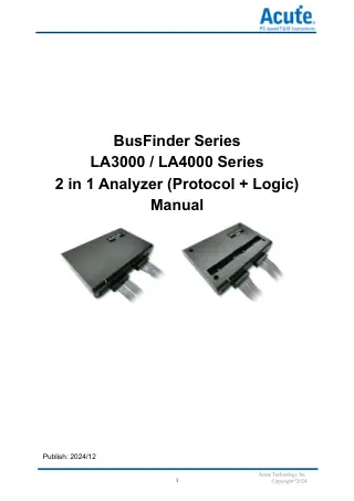 Acute BusFinder LA3000/LA4000 2 in 1 AnalyzerOfficial user manual for the BusFinder LA3000/LA4000 2 in 1 Analyzer, version 2024/12.Covers installation, probe options, software setup, and protocol...
Domande e risposte
-
What Host Interface and OS Are Supported?
It connects over USB 3.0 to Windows 7/8/10/11 PCs (64-bit software only). Minimum 8 GB RAM, 16 GB recommended.
-
Are Active Probes Required?
Not always. Acute supplies protocol-specific active probes for easier connection to the target, and some options can also use flying leads. Triggering and statistics are provided by each protocol option.
-
Can It Export Decoded Data for Analysis?
Yes. You can export decoded reports to TXT/CSV for scripting and automated analysis.
-
What’s the Difference Between Analyser, Logger and Monitor Modes?
Each mode captures differently:
- Analyser shows protocol traffic in real time.
- Logger streams to SSD for very large captures.
- Monitor records rare, trigger-only events from device memory.
-
Is UFS Supported?
Yes, as a UFS 2.1 option on the BF7264B+ and BF7264 Pro. Acute lists UFS only for those two models.
-
How Is It Different From Oscilloscope-Based Decode?
Oscilloscopes are best for physical-layer compliance and eye/jitter analysis. BusFinder focuses on long-form protocol logging, hardware decode and statistics.
-
Can It Run as a Pure Logic Analyser?
Yes, it captures 64 channels with timing/state and overlays bus decodes; it can also stack with a DSO as an MSO.
-
How Does Transitional Storage Help?
Transitional storage avoids heavy decompression after capture, so results show as soon as the capture is processed. It does reduce the number of usable channels.
No questions match your search.
