Passer aux informations produits
1 de 3

Mikroelektronika d.o.o.

Carte à clic VCP Monitor 3

Carte à clic VCP Monitor 3

Carte de mesure de précision de tension, de courant et de puissance
SKU: MIKROE-4222
Prix habituel
€26,95 EUR hors taxes
Prix habituel Prix promotionnel
€26,95 EUR hors taxes
En vente Épuisé
Frais d'expédition calculés à l'étape de paiement.
If no stock shown above, check availability
Afficher tous les détails
} ] }

Overview

Le VCP Monitor 3 Click Board™ est un Click Board™ de mesure de tension, de courant et de puissance de haute précision avec une entrée capable de prendre jusqu'à 15 V. Il est équipé du LTC2947, d'Analog Devices, un moniteur de puissance et d'énergie de haute précision avec une résistance de détection interne prenant en charge jusqu'à ±30 A. Trois ADC delta-sigma internes sans latence garantissent une mesure précise de la tension et du courant, avec une précision de tension jusqu'à 0,5 % et de courant de 1 %, tandis que la multiplication analogique à large bande passante fournit une mesure de puissance précise dans une large gamme d'applications. Une résistance de détection interne de 300 μΩ compensée en température minimise la perte d'efficacité tout en permettant une mesure de courant de haute précision sur toute la plage de températures. Toutes les valeurs mesurées sont stockées dans des registres internes accessibles via l'interface I2C ou SPI sélectionnable. Toutes ces fonctionnalités font du VCP Monitor 3 Click l'outil idéal pour une utilisation dans des applications telles que les mesures industrielles, les véhicules électriques, les systèmes photovoltaïques, les infrastructures de télécommunications, les serveurs, etc.

Le VCP Monitor 3 Click est pris en charge par une bibliothèque compatible mikroSDK, qui comprend des fonctions qui simplifient le développement logiciel. Cette Click Board™ est un produit entièrement testé, prêt à être utilisé sur un système équipé du socket mikroBUS™.

How Does The VCP Monitor 3 Click Board™  Work?

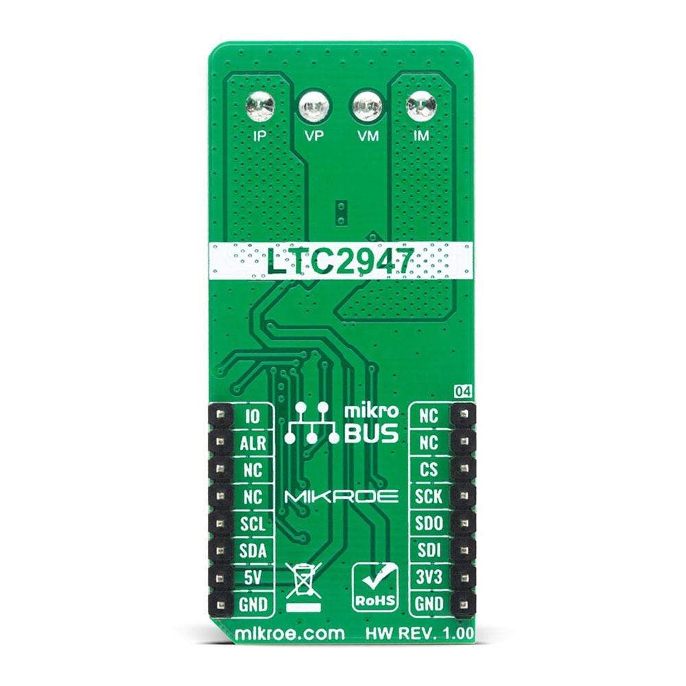
The VCP Monitor 3 Click Board™  is a high precision power and energy monitor with the capability of supporting up to ±30A with a low 9mA offset. Input Range allows 0V to 15V bus voltages with 0.5% measurement accuracy. The LTC2947 is responsible for measuring current, voltage, power, charge and energy with 1% current and charge accuracy and 1.2% power and energy accuracy. Additional features include an alert indication in case some of the thresholds are exceeded, and user-configurable GPIO pin for various functions. The LTC2947 possesses internal 300µΩ, temperature-compensated sense resistor that minimizes efficiency loss and external components, simplifying energy measurement applications while enabling high accuracy current measurement over the full temperature range. All measured quantities are stored in internal registers accessible via the selectable I2C/SPI interface. The LTC2947 features programmable high and low thresholds for all measured quantities to reduce digital traffic with the host.

vcp monitor 3 click inner

Measuring a total of seven parameters: current, voltage, power, charge (coulombs), energy, and run time, as well as its own chip temperature, makes this click board excellent for high variety of applications. Main chip LTC2947 includes three no latency delta-sigma analog-to-digital converters to simultaneously measure current, voltage, and power. It also measures die temperature and derives the accumulated quantities charge, energy, and time using an on-board oscillator. It stores these values in internal registers that can be read out via the serial interface, configurable as either I2C or SPI. The LTC2947 keeps track of the minimum and maximum measured values for each of the measured quantities. Thresholds can be set for each parameter, and the LTC2947 will set the corresponding bit in the Alert register and optionally alert the host by pulling low on the ALERT pin when a threshold is exceeded. A GPIO pin is included that can be used for four different purposes. It can be configured as a general-purpose-logic input or output, as an output to automatically control a fan based on the LTC2947's internal silicon temperature measurement or as an input to enable and disable accumulation of charge, energy, and time.

The LTC2947 measures each input with an ADC specifically tailored for the task. Connections labeled as IM (Negative) and IP (Positive) are high side current sense inputs and must be tied in series with the load intended for the measurement. Voltage sense inputs VM (Negative) and VP (Positive) should be connected parallel to the load for a second ADC to measure the differential voltage between those two terminals. More information about the LTC2947's functionality, electrical specifications, and typical performance can be found in the attached datasheet.

VCP Monitor 3 Click supports both SPI and I2C communication interfaces, allowing it to be used with a wide range of different MCUs. The communication interface can be selected by moving SMD jumpers grouped under the COMM SEL to an appropriate position (SPI or I2C). The slave I2C address can also be configured by SMD jumpers under ADDR SEL when the Click board™ is operated in the I2C mode.

This Click Board™ is designed to be operated with both 3.3V and 5V logic levels that can be selected via VCC SEL jumper. This allows for both 3.3V and 5V capable MCUs to use the communication lines properly.

SPECIFICATIONS

Type Measurements
Applications Can be used in applications including Servers, Telecom Infrastructure, Industrial, Electric Vehicles, Photovoltaics and more.
On-board modules LTC2947 - a high precision power and energy monitor with an internal sense resistor, from Analog Devices
Key Features Measures Current with ±30A range, Voltage with 0V to 15V input range, Power, Charge, Energy. Provides 0.5% Voltage Accuracy, 1% Current and Charge Accuracy, 1.2% Power and Energy Accuracy, Alerts When Thresholds Exceeded.
Interface I2C,SPI,GPIO
Compatibility mikroBUS
Click board size L (57.15 x 25.4 mm)
Input Voltage 3.3V or 5V


PINOUT DIAGRAM

This table shows how the pinout on VCP Monitor 3 Click corresponds to the pinout on the mikroBUS™ socket (the latter shown in the two middle columns).

Notes Pin Mikrobus logo.png Pin Notes
  NC 1 AN PWM 16 IO GPIO
  NC 2 RST INT 15 ALR Alert pin
SPI Chip Select CS 3 CS RX 14 NC  
SPI Clock SCK 4 SCK TX 13 NC  
SPI Data OUT MISO 5 MISO SCL 12 SCL I2C Clock
SPI Data IN MOSI 6 MOSI SDA 11 SDA I2C Data
Power Supply 3.3V 7 3.3V 5V 10 5V Power Supply
Ground GND 8 GND GND 9 GND Ground

ONBOARD SETTINGS AND INDICATORS

Label Name Default  Description
LD1 PWR - Power LED Indicator
LD2 GPIO - User-configurable LED Indicator
LD3 ALERT - Alert LED Indicator
JP1 VCC SEL Left Power Supply Voltage Selection 3V3/5V, left position 3v3, right position 5v
JP2 - JP5 COMM SEL Left Communication interface selection: left position - SPI, right position - I2C
JP6, JP7 ADDR SEL Right I2C Slave Address selection: left position 0, right position 1

VCP MONITOR 3 CLICK ELECTRICAL SPECIFICATIONS

Description Min Typ Max Unit
Digital Supply Voltage 1.8 3.3 5.5 V
Input Differential Voltage Range (VP - VM) -0.3 - 15 V
Input Current Through IP and IM -30 - 30 A
Internal Sense Resistor 140 300 450 µΩ

MikroElektronika Software Development Kit. To ensure proper operation of mikroSDK compliant Click board™ demo applications, mikroSDK should be downloaded from the LibStock and installed for the compiler you are using.

Frequently Asked Questions

Have a Question?

Be the first to ask a question about this.

Ask a Question

Customer Reviews

Be the first to write a review
0%
(0)
0%
(0)
0%
(0)
0%
(0)
0%
(0)