
Mikroelektronika d.o.o.
Planche à clic Stepper
Planche à clic Stepper
SKU: MIKROE-1528
Impossible de charger la disponibilité du service de retrait


Overview
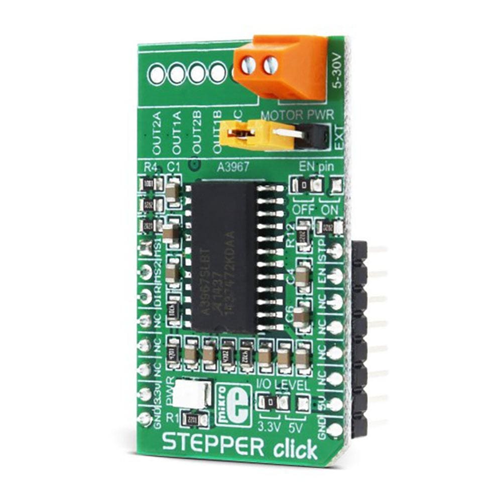
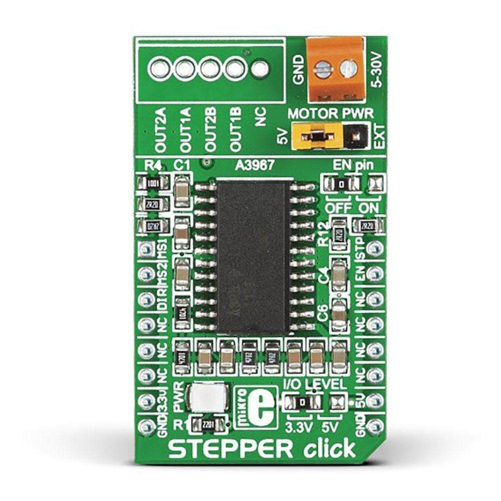
Introduce precision motor control to the user device with Stepper Click Board™. This stepper motor driver board includes an A3967SLBT stepper motor driver that allows controlling bipolar step motors in full-, half-, quarter- and eighth-step modes. The maximum output drive capability is 30V and nearly '500 mA.
It also features an integrated translator that supports the easy implementation of the A3967SLBT microstepping driver. The package is offered with two sets of connectors: a B5B-XH-A connector and a pair of screw terminals. Both types of connectors are delivered unsoldered with the package and can be used as a connecting option. The user can use the j3 jumper to select whether the power of the motor driver comes with the onboard or external power supply.
The Stepper Click Board™ supports either a 3.3V or 5V power supply, which can be selected through the zero-ohm J1 SMD jumper (3.3V is the default position). The user can also choose to use the motor driver.
Downloads
Introduisez le contrôle de précision du moteur dans l'appareil utilisateur avec Stepper Click Board™ . Cette carte de commande de moteur pas à pas comprend un pilote de moteur pas à pas A3967SLBT qui permet de contrôler les moteurs pas à pas bipolaires en modes pas à pas complet, demi-pas, quart de pas et huitième de pas. La capacité de sortie maximale est de 30 V et de près de 500 mA.
Il dispose également d'un traducteur intégré qui prend en charge la mise en œuvre facile du pilote de micro-pas A3967SLBT. Le package est proposé avec deux jeux de connecteurs : un connecteur B5B-XH-A et une paire de bornes à vis. Les deux types de connecteurs sont livrés non soudés avec le package et peuvent être utilisés comme option de connexion. L'utilisateur peut utiliser le cavalier j3 pour sélectionner si l'alimentation du pilote de moteur est fournie par l'alimentation embarquée ou externe.
Le Stepper Click Board™ prend en charge une alimentation de 3,3 V ou 5 V, qui peut être sélectionnée via le cavalier CMS J1 zéro ohm (3,3 V est la position par défaut). L'utilisateur peut également choisir d'utiliser le pilote de moteur.
| General Information | |
|---|---|
Part Number (SKU) |
MIKROE-1528
|
Manufacturer |
|
| Physical and Mechanical | |
Weight |
0.035 kg
|
| Other | |
EAN |
8606015075075
|
Frequently Asked Questions
Have a Question?
Be the first to ask a question about this.