


Mikroelektronika d.o.o.
Carte à clic PowerBank 2
Carte à clic PowerBank 2
SKU: MIKROE-4116
Impossible de charger la disponibilité du service de retrait
Overview
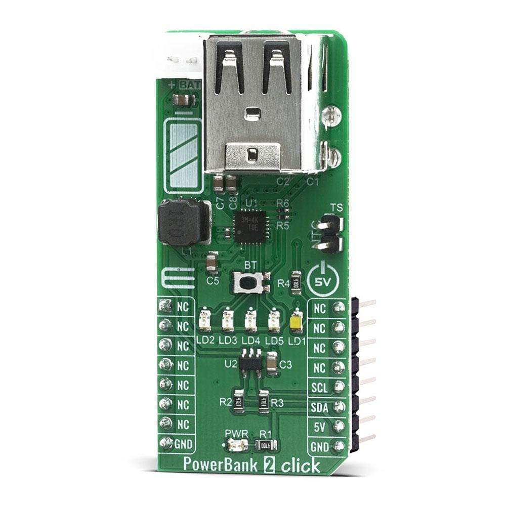
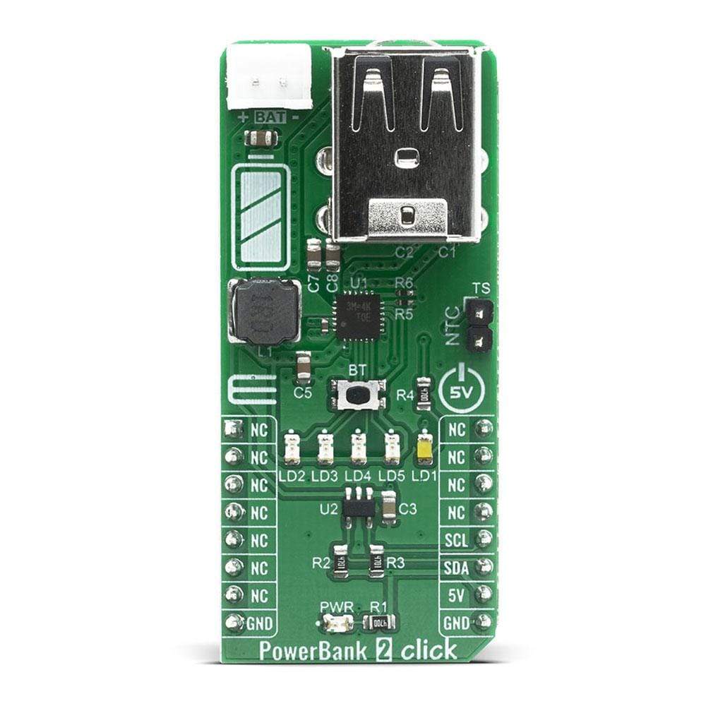
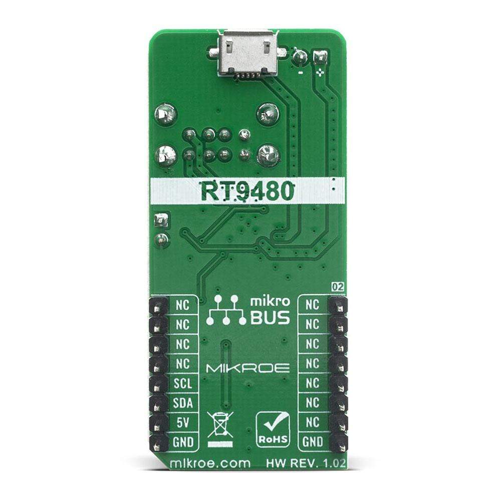
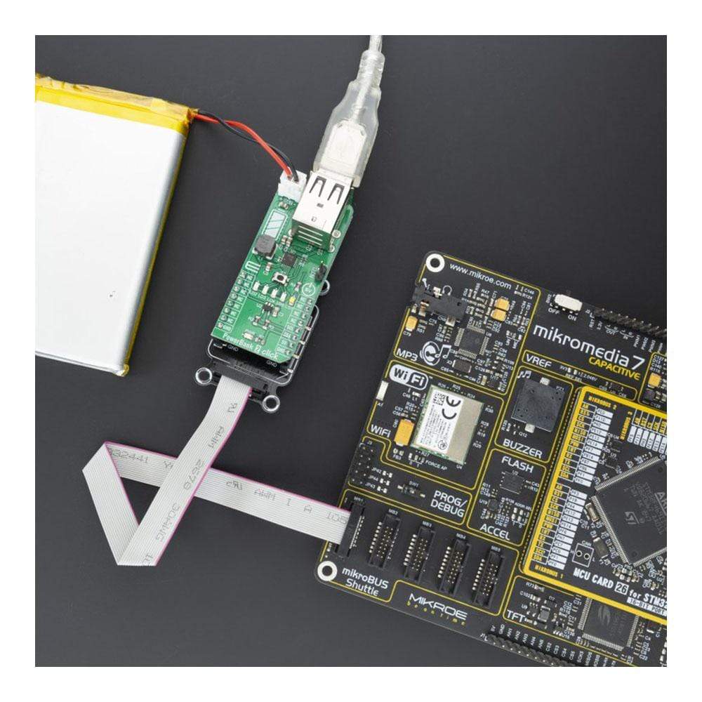
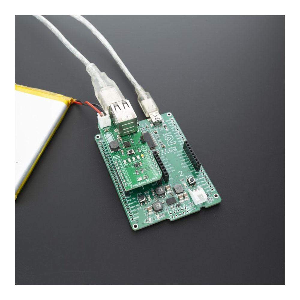
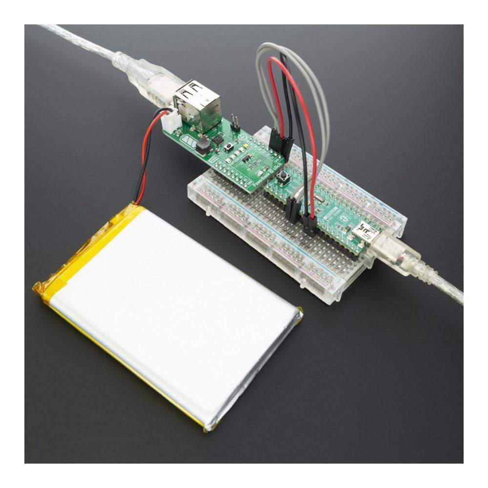
The PowerBank 2 Click Board™ is equipped with the RT9480, a highly integrated and easy to use power solution for Li-ion power bank and other powered handheld applications. It’s usually called EZPBS (Easy to Use PowerBank Solution). This single-chip includes a linear charger, a synchronous Boost with dual output load management and a torch function support. The battery volume and the state of charging and discharging can be indicated by 4 LEDs.
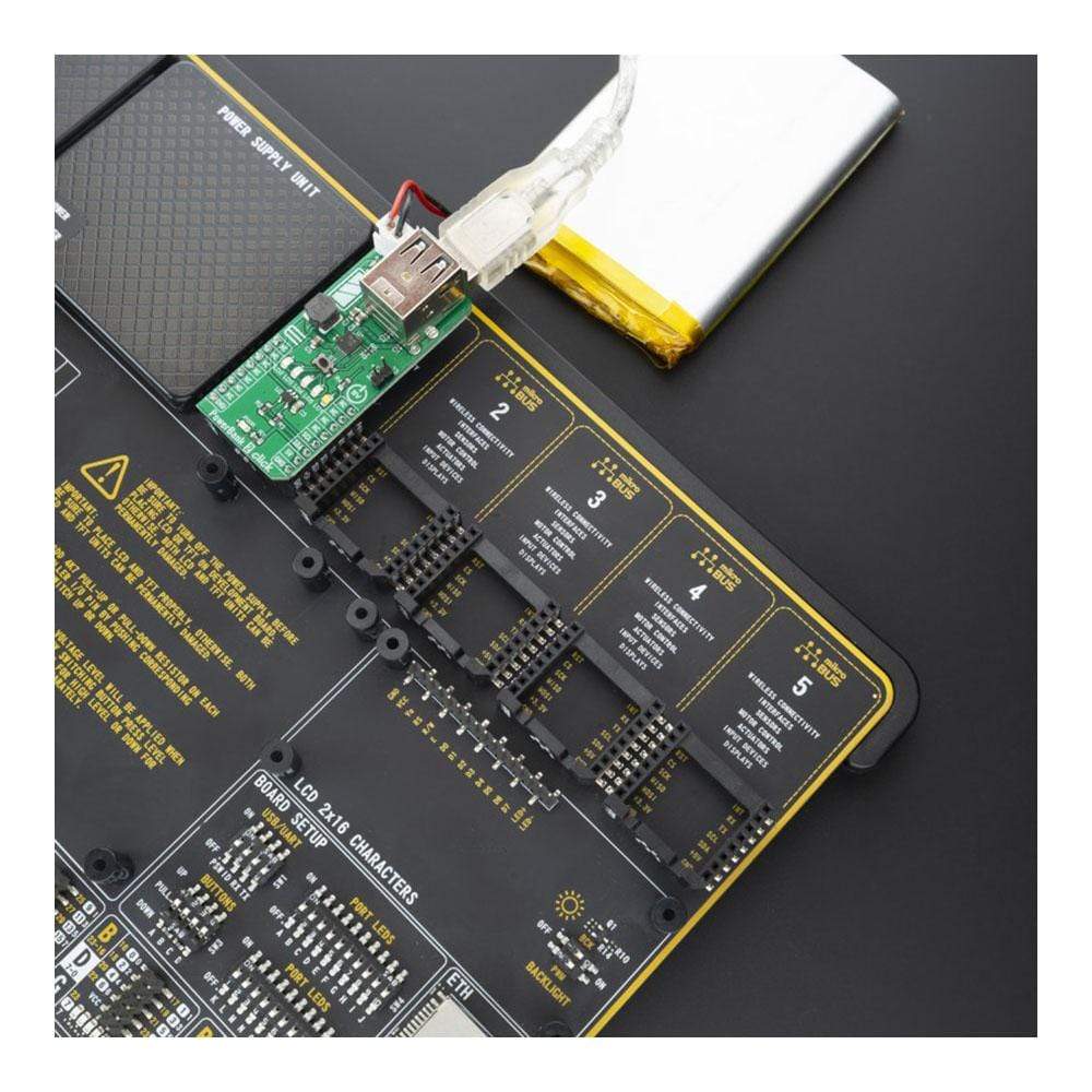
PowerBank 2 Click is supported by a mikroSDK compliant library, which includes functions that simplify software development. This Click Board™ comes as a fully tested product, ready to be used on a system equipped with the mikroBUS™ socket.
Downloads
Le PowerBank 2 Click Board ™ est équipé du RT9480, une solution d'alimentation hautement intégrée et facile à utiliser pour les banques d'alimentation Li-ion et autres applications portables alimentées. Elle est généralement appelée EZPBS (Easy to Use PowerBank Solution). Cette puce unique comprend un chargeur linéaire, un Boost synchrone avec gestion de charge à double sortie et une fonction de torche. Le volume de la batterie et l'état de charge et de décharge peuvent être indiqués par 4 LED.
PowerBank 2 Click est pris en charge par une bibliothèque compatible mikroSDK, qui comprend des fonctions qui simplifient le développement logiciel. Cette Click Board™ est un produit entièrement testé, prêt à être utilisé sur un système équipé de la prise mikroBUS™.
| General Information | |
|---|---|
Part Number (SKU) |
MIKROE-4116
|
Manufacturer |
|
| Physical and Mechanical | |
Weight |
0.026 kg
|
| Other | |
EAN |
8606018717446
|
Frequently Asked Questions
Have a Question?
Be the first to ask a question about this.