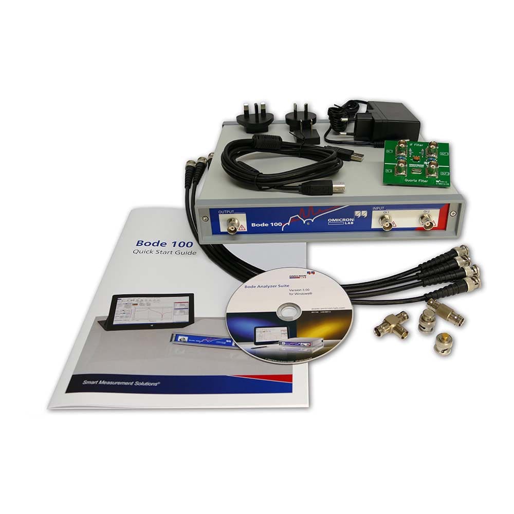
Key Features
Overview
Revolutionise Your Measurements
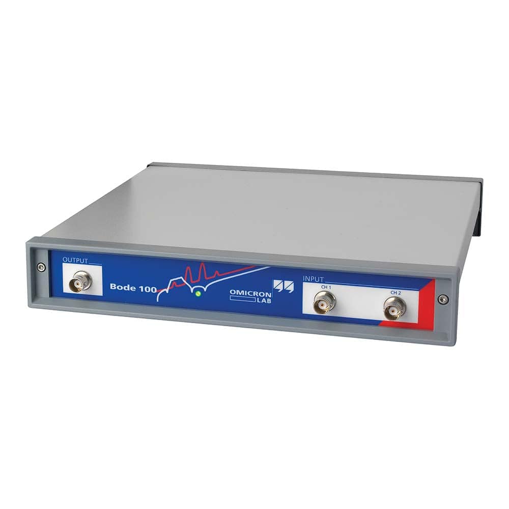
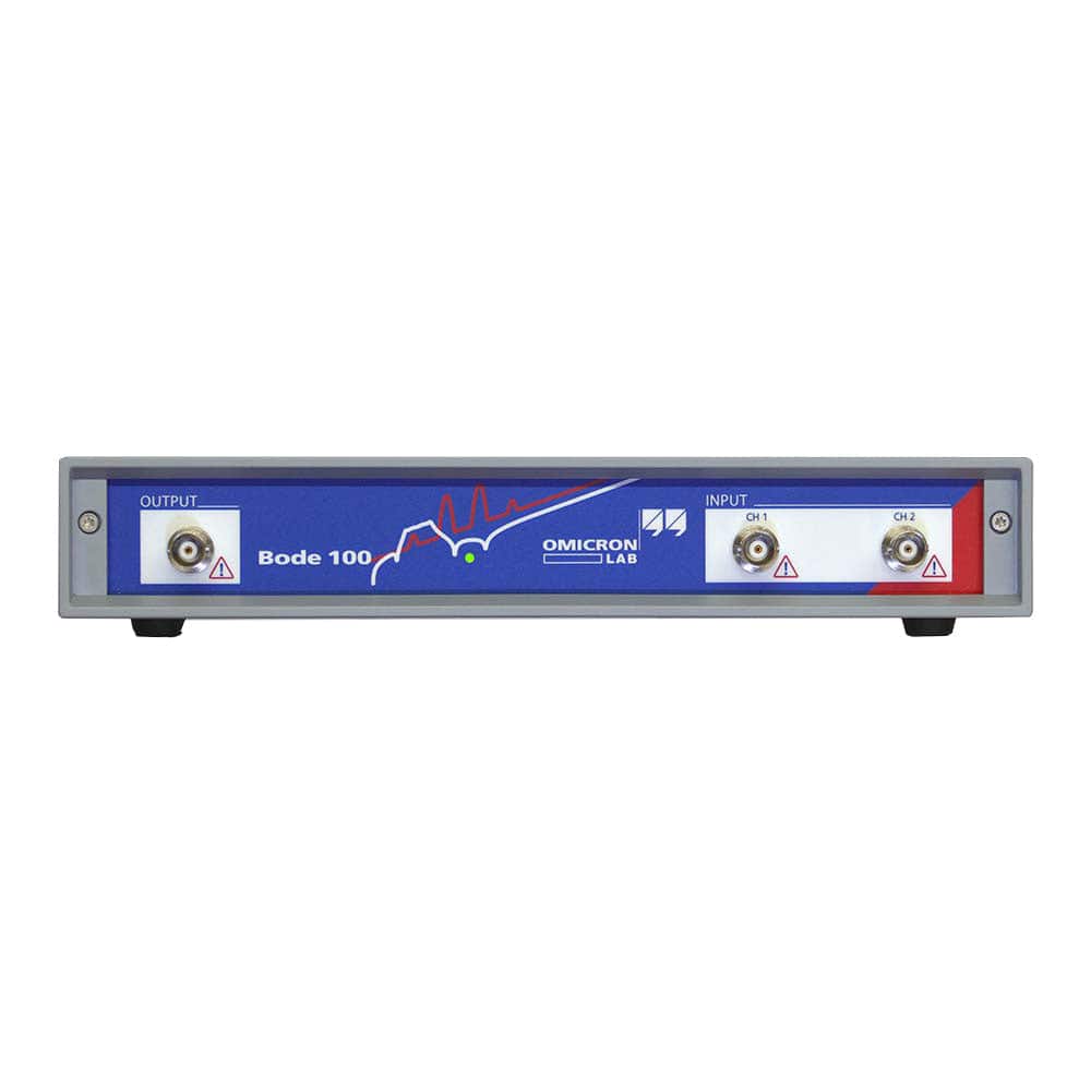
Discover an instrument that redefines versatility in the realm of test and measurement. Introducing the Bode-100, the essential tool you never knew you needed until now. Offering unparalleled performance in a compact form factor, this instrument promises to elevate the quality, precision, and efficiency of your work.
Unmatched Versatility
- Vector Network Analyser (VNA)
- Frequency Response Analyser
- Gain/Phase Meter
- Impedance Analyser
Deep Dive Into Features
The Omicron-Lab Bode-100 doesn't just stop at multifunctionality. Dive deeper into the extensive features it brings to the table:
- Sinusoidal Signal Generation: Precisely measures the response of your device under test (DUT) by generating sinusoidal signals across varied frequencies.
- Diverse Measurement Modes: From transmission/reflection, gain, and impedance measurements, choose the mode that best fits your needs.
- Complex Analysis: Measure active and passive circuits' complex gain, impedance, and admittance.
- S-Parameter Sweep: Analyse the swept S-parameters of electronic circuits and filters easily.
- Group Delay Characteristics: Understanding signal delay in your circuits is made simpler.
Ready to Elevate Your Testing Game?
Make sure to integrate the future of test and measurement instruments into your lab. Order your Bode-100 today!
Downloads
Le Bode 100 d'Omicron-Lab : une centrale de test et de mesure multifonctionnelle
Révolutionnez vos mesures
Découvrez un instrument qui redéfinit la polyvalence dans le domaine des tests et des mesures. Présentation du Bode-100 , l'outil essentiel dont vous n'aviez jamais pensé avoir besoin jusqu'à présent. Offrant des performances inégalées dans un format compact, cet instrument promet d'élever la qualité, la précision et l'efficacité de votre travail.
Polyvalence inégalée
- Analyseur de réseau vectoriel (VNA)
- Analyseur de réponse en fréquence
- Compteur de gain/phase
- Analyseur d'impédance
Plongée en profondeur dans les fonctionnalités
Le Bode-100 d'Omicron-Lab ne se limite pas à sa multifonctionnalité. Découvrez plus en détail les nombreuses fonctionnalités qu'il propose :
- Génération de signaux sinusoïdaux : mesure précisément la réponse de votre appareil testé (DUT) en générant des signaux sinusoïdaux sur différentes fréquences.
- Différents modes de mesure : des mesures de transmission/réflexion, de gain ou d'impédance, choisissez le mode qui correspond le mieux à vos besoins.
- Analyse complexe : mesurez le gain complexe, l'impédance, l'admittance et bien plus encore, des circuits actifs et passifs.
- Balayage des paramètres S : analysez facilement les paramètres S balayés des circuits électroniques et des filtres.
- Caractéristiques du retard de groupe : la compréhension du retard du signal dans vos circuits est simplifiée.
Perfectionnement des mesures d'impédance
Avec sept méthodologies de mesure d'impédance distinctes, sélectionnez celle qui convient parfaitement à votre tâche spécifique.
Visualisez comme jamais auparavant
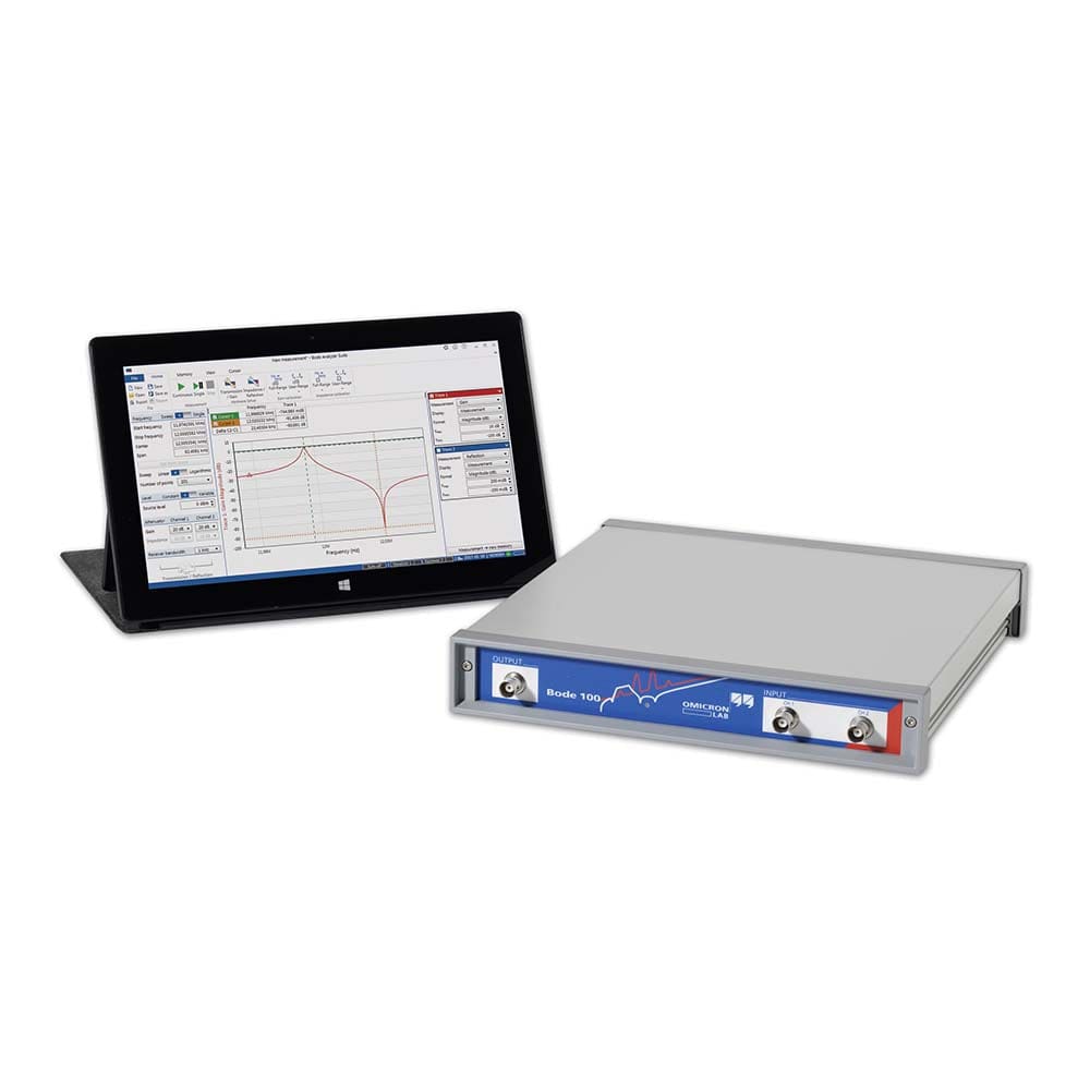
Grâce au logiciel Bode Analyser Suite , visualisez vos données sous différents formats, notamment les diagrammes Smith, Polar et Nyquist. Que vous recherchiez des balayages de fréquence linéaires ou logarithmiques, ce logiciel vous permet de définir et de personnaliser vos mesures dans les moindres détails.
Pourquoi Bode-100 ?
- Solution tout-en-un : dites adieu à la jonglerie entre plusieurs instruments. Le Bode-100 les regroupe en un seul.
- Interface conviviale : la gestion des nombreuses fonctionnalités est un jeu d'enfant avec le logiciel Bode Analyser Suite.
- La précision à son meilleur : des résultats précis, à chaque fois.
- Compact mais robuste : soyez conscient de sa taille ; le Bode-100 est une centrale électrique.
Prêt à améliorer vos tests ?
Assurez-vous d'intégrer l'avenir des instruments de test et de mesure dans votre laboratoire. Commandez votre Bode-100 dès aujourd'hui !
| General Information | |
|---|---|
Part Number (SKU) |
P0005755
|
Manufacturer |
|
| Physical and Mechanical | |
Weight |
2.0 kg
|
| Other | |
Warranty |
|
HS Code Customs Tariff code
|
|
EAN |
5055383623648
|
Frequently Asked Questions
Have a Question?
-
What unique competitive advantages does the Bode-100 offer over more expensive VNA solutions
The Bode-100's primary competitive advantages include its unmatched low-frequency performance starting from 1 Hz (impossible with traditional VNAs), silent fanless operation, compact portable design, and exceptional price-performance ratio. Whilst expensive VNAs excel at high-frequency applications, the Bode-100 dominates the low-frequency domain crucial for power electronics and EMC applications. Its multifunctional capability eliminates the need for separate FRA and impedance analysers, providing significant cost savings. The combination of professional performance, comprehensive software, and accessible pricing makes it the optimal choice for engineers not requiring frequencies above 50 MHz.
-
What software and connectivity options are available with the Bode-100?
The Bode-100 includes the comprehensive Bode Analyzer Suite software providing measurement control, data analysis, and documentation capabilities. The software features Smith chart displays, polar plots, memory curves, mathematical functions, and SPICE model generation. Connectivity is provided via USB interface with full remote control capabilities. The software supports data export to standard formats compatible with MATLAB, Excel, and other analysis tools. Regular software updates ensure compatibility with modern operating systems and add new measurement capabilities.
-
How does the Bode-100 compare to low-cost VNA alternatives like the NanoVNA?
Whilst instruments like the NanoVNA offer basic VNA functionality at very low cost, the Bode-100 provides professional-grade performance with superior dynamic range, accuracy, and frequency stability. The Bode-100's 1 Hz starting frequency, >100 dB dynamic range, and professional software suite far exceed the capabilities of amateur-grade instruments. Most importantly, the Bode-100 includes comprehensive technical support, calibration services, and application expertise that are essential for professional applications. For critical measurements requiring repeatable, traceable results, the Bode-100 represents the minimum professional standard.
-
What calibration procedures does the Bode-100 require, and how accurate are the results?
The Bode-100 supports multiple calibration procedures including full-range calibration using open/short/load standards and user-range calibration for specific frequency spans. After proper calibration, the instrument achieves gain accuracy of <0.1 dB and phase accuracy of <0.5° in the user-calibrated range. The calibration process is automated through the Bode Analyzer Suite software, and verification standards are included to ensure measurement integrity. For maximum accuracy, regular calibration is recommended, particularly when changing measurement configurations.
-
How does the Bode-100 handle EMC filter and component characterisation?
The Bode-100 excels at EMC filter characterisation by measuring both common-mode and differential-mode insertion loss across its full frequency range. Using the B-WIC and B-SMC impedance adapters, it can accurately characterise individual filter components including common-mode chokes, X and Y capacitors, and complete filter assemblies. The measurement data can be used to create accurate SPICE models for filter simulation and optimisation. Its ability to detect parasitics and resonances makes it invaluable for EMC compliance and filter design validation.
-
What advantages does the Bode-100 offer for power supply engineers specifically?
The Bode-100 provides unique advantages for power supply engineers through its ability to perform non-invasive stability measurements using voltage injection techniques. It can measure loop gain, output impedance, PSRR, and input impedance of switching power supplies without disrupting normal operation. The instrument's high side-band rejection and dynamic range enable accurate measurements on noisy switching converters, whilst its speed allows comprehensive characterisation across multiple operating points. Integration with Biricha's WDS software enables direct import of measurement data for automatic compensation design.
-
Can the Bode-100 VNA perform automated measurements and integrate with existing test systems?
Yes, the Bode-100 features comprehensive automation capabilities through its .NET-based Bode Automation Interface and SCPI-compatible command set. This enables seamless integration into automated test equipment (ATE) systems and custom measurement applications. The automation interface supports programmatic control of all measurement functions, calibration procedures, and data acquisition, making it suitable for production testing environments and research applications requiring repeated measurements.
-
What specific applications is the Bode-100 VNA particularly well-suited for?
The Bode-100 excels in several specialised applications: power supply stability analysis through loop gain measurements, DC/DC converter characterisation, EMC filter insertion loss testing, component parasitics analysis, PSRR measurements, RFID and NFC antenna tuning, transformer and inductor analysis, and power delivery network (PDN) impedance characterisation. Its low-frequency capability makes it indispensable for power electronics engineers, whilst its impedance analysis features are valuable for component manufacturers and EMC compliance testing.
-
How does the Bode-100's performance compare to high-end VNAs from manufacturers like Keysight and Rohde & Schwarz?
Whilst premium VNAs from Keysight (such as the E5061B costing £50,000+) and Rohde & Schwarz offer broader frequency ranges extending into millimetre-wave frequencies, the Bode-100 provides superior performance in its specialised low-frequency domain at a fraction of the cost. For applications within its 1 Hz to 50 MHz range, the Bode-100 delivers comparable accuracy to these high-end instruments, particularly excelling in power supply and EMC applications where its low-frequency capabilities are paramount. The Bode-100's price-performance ratio is unmatched for applications not requiring frequencies above 50 MHz.
-
What makes the Omicron-Lab Bode-100 VNA unique compared to traditional vector network analysers?
The Bode-100 VNA distinguishes itself through its exceptional low-frequency capability starting from 1 Hz, whilst most traditional VNAs begin at much higher frequencies. This unique characteristic makes it particularly valuable for power supply analysis, DC/DC converter stability testing, and EMC filter characterisation. Unlike conventional VNAs that focus primarily on RF applications, the Bode-100 bridges the gap between traditional frequency response analysers and vector network analysers, offering the benefits of both in a single, compact instrument. Its multifunctional design eliminates the need for separate instruments, providing significant cost savings and laboratory space efficiency.
-
What is the warranty for the Bode-100?
The Bode-100 comes with a 2-year warranty.
-
Is the Bode-100 compatible with any software?
The Bode-100 is compatible with Omicron-Lab's Bode-Analyzer software, which allows for easy data analysis and visualization.
-
What is the maximum measurement speed of the Bode-100?
The Bode-100 has a measurement speed of up to 10 measurements per second.
-
What is the frequency range of the Bode-100?
The Bode-100 has a frequency range of 1Hz to 50MHz.
-
What types of measurements can the Bode-100 perform?
The Bode-100 can perform a wide range of measurements, including small-signal stability, input and output impedance, gain and phase margin, power factor, total harmonic distortion, and conducted and radiated emissions.
-
What is the Omicron-Lab Bode-100?
The Omicron-Lab Bode-100 is a vector network analyzer (VNA) designed for small-signal stability and frequency-domain analysis of electronic circuits.

