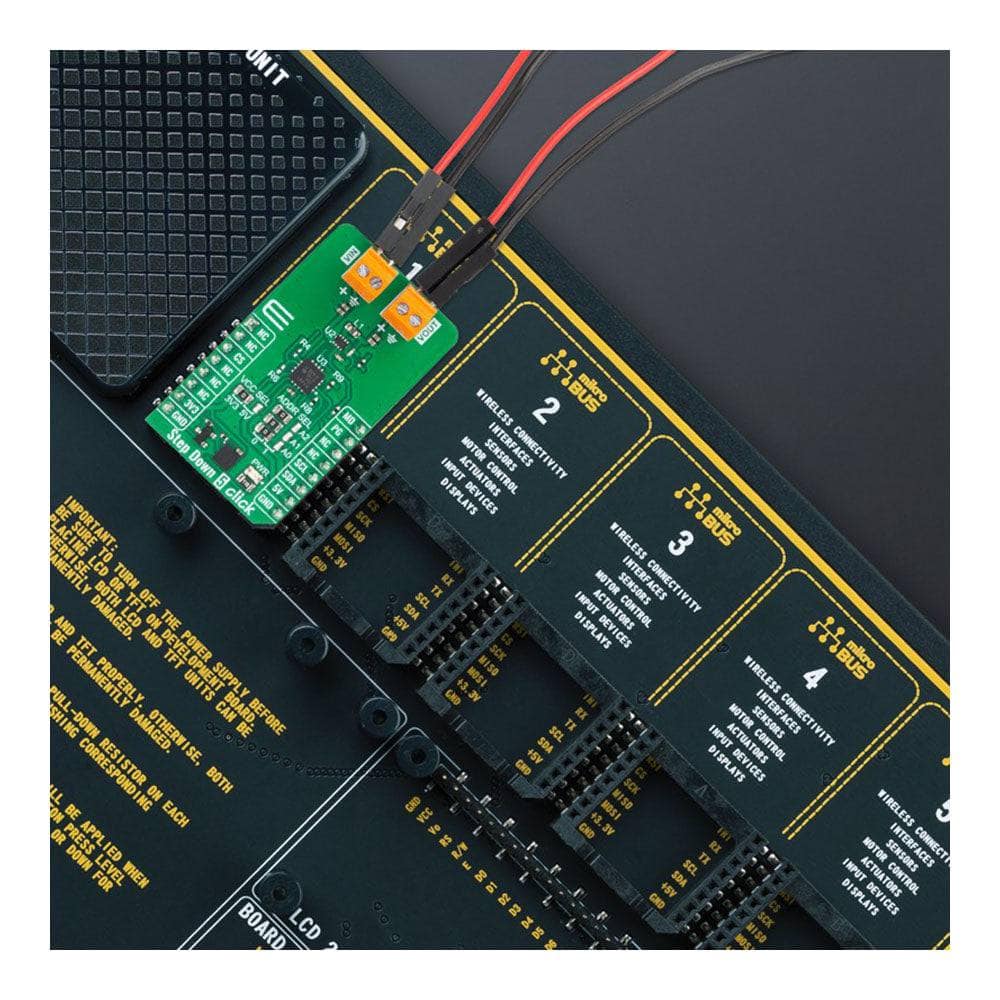
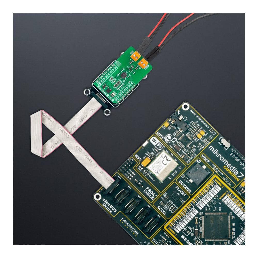
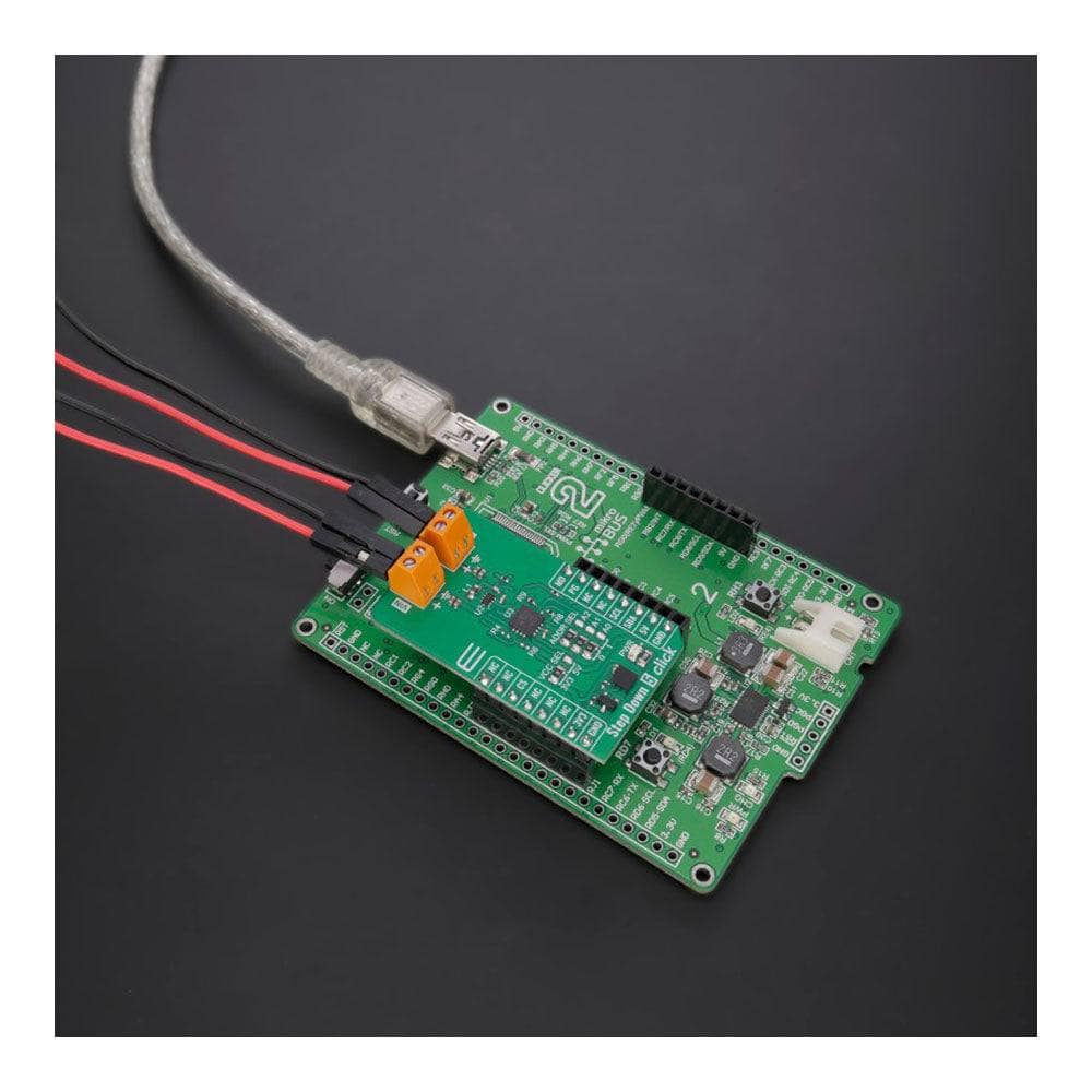
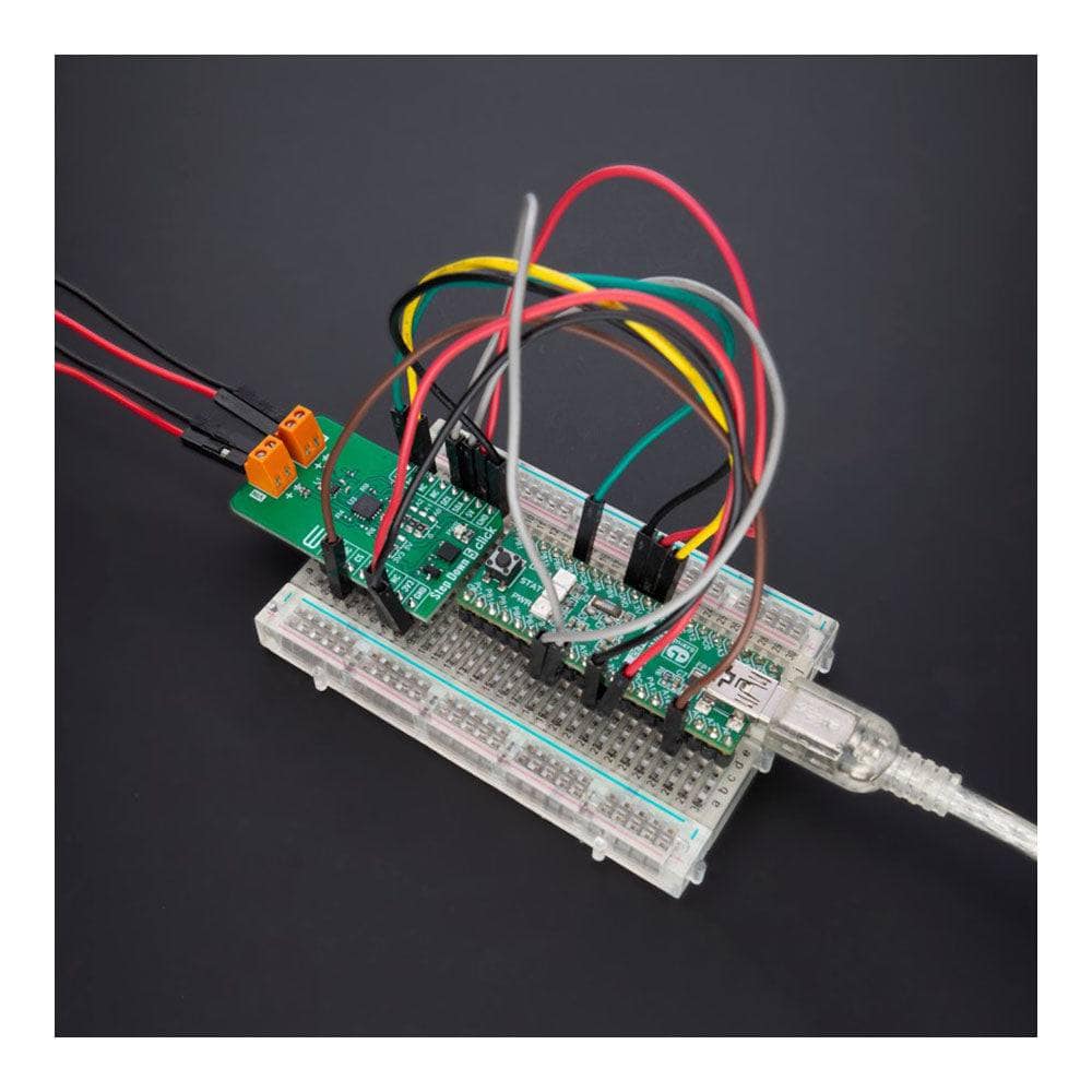
Étape 5 Cliquez sur le tableau
Key Features
- Utilisation d'une topologie de contrôle en mode courant de crête, courant de sortie jusqu'à 0,5 A, tension de sortie sélectionnable via un potentiomètre numérique, haute précision et efficacité, fréquence de commutation fixe, fonctionnement PWM ou PWM/PFM en Porc, indicateur de bonne alimentation, et plus encore
- Basé sur le TPS628510 - convertisseur abaisseur synchrone de Texas Instruments
- Peut être utilisé pour des solutions de conversion de puissance dans les applications d'automatisation et de contrôle, les capteurs industriels, les équipements de test et de mesure, les appareils portables à faible consommation, etc.
- mikroBUS : interfaces I2C et PWM
Présentation de la carte Step Down 5 Click Board™ : conversion de tension à haut rendement simplifiée
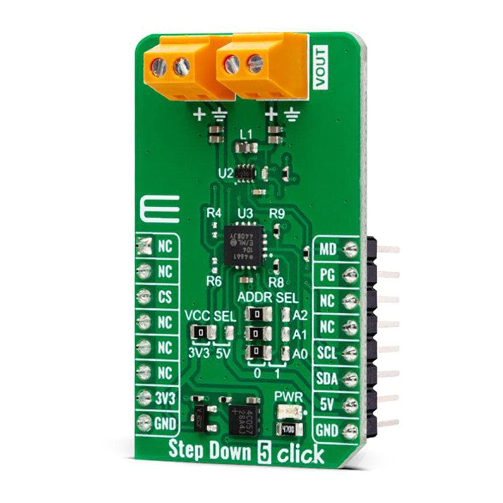
Découvrez la puissance de la Step Down 5 Click Board™, une carte complémentaire compacte et efficace qui convertit sans effort des niveaux de tension plus élevés en niveaux plus faibles. Cette carte incroyable est équipée du TPS628510, un convertisseur CC/CC abaisseur synchrone haut de gamme de Texas Instruments. Spécialement conçu pour les applications où une efficacité élevée est essentielle, le TPS628510 fournit jusqu'à 500 mA de courant de sortie et fonctionne avec des tensions d'entrée allant de 2,7 V à 6 V.
Fonctionnalités avancées pour des performances optimales
Découvrez la flexibilité de la carte Step Down 5 Click Board™ avec sa fréquence de commutation fixe de 2,25 MHz, son mode de fonctionnement PWM forcé ou PWM/PFM sélectionnable et sa tension de sortie réglable de 0,6 V à 5,5 V, le tout réglé via un potentiomètre numérique configurable en I2C. De plus, la carte dispose d'un signal Power Good pour indiquer une tension de sortie stabilisée, garantissant ainsi que votre conversion de tension est précise et fiable.
Idéal pour une large gamme d'applications
Des applications d'automatisation et de contrôle aux capteurs industriels, aux équipements de test et de mesure et aux appareils portables à faible consommation, le Step Down 5 Click Board™ est la solution parfaite pour tous vos besoins de conversion de puissance.
Intégration transparente avec mikroSDK
Supporté par une bibliothèque compatible mikroSDK, le Step Down 5 Click Board™ simplifie le développement logiciel avec une suite de fonctions conçues pour votre confort. En tant que produit entièrement testé, ce Click board™ est prêt à être utilisé avec n'importe quel système équipé de la prise mikroBUS™, rendant la conversion de tension plus facile que jamais.
How Does The Step Down 5 Click Board™Work?
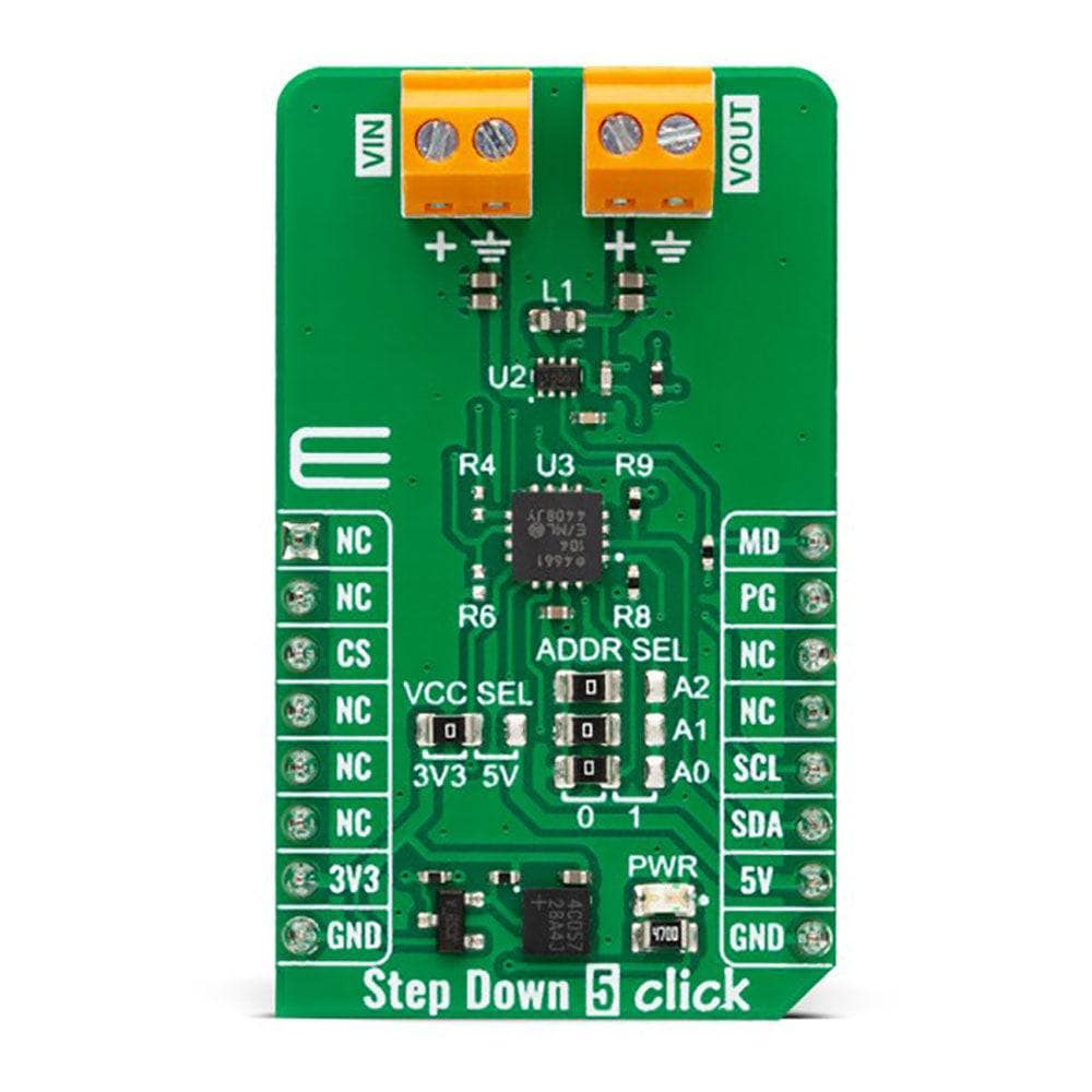
The Step Down 5 Click Board™ is based on the TPS628510, a synchronous step-down converter from Texas Instruments, providing interface-configurable output voltage range from 0.6V to 5.5V suitable for point-of-load and post-regulation applications. This synchronous switch mode power converter is based on a peak current mode control topology and achieves fast and stable operation with an internally compensated control loop. It provides up to 0.5A load current over a wide input supply range from 2.7V to 6V and has excellent load and line regulation. In addition, it is characterized by high efficiency over a wide range of load output voltage from 0.6V to 5.5V, which can be easily adjusted using a digital potentiometer, the MCP4661 from Microchip.
The TPS628510 supports forced fixed frequency PWM operation with the MD pin of the mikroBUS™ socket set to a high logic level. Its switching frequency is internally fixed at 2.25MHz. When the MD pin is set to a low logic level, the TPS628510 operates in power save mode (PFM) at a low output current and automatically transfers to fixed-frequency PWM mode at a higher output current. In PFM mode, the switching frequency decreases linearly based on the load to sustain high efficiency down to a very low output current. Alternatively, the TPS628510 can be synchronized to an external clock signal from 1.8MHz to 4MHz, applied to the MD pin. An internal PLL allows you to change from an internal clock to an external clock during operation.
Besides the operational mode selection pin, this Click board™ also has a power-good function routed to the PG pin of the mikroBUS™ socket, indicating that the output reached desired regulation and the possibility for the MCP4661 to choose the least significant bit (LSB) of its I2C slave address by positioning SMD jumpers labelled as ADDR SEL to an appropriate position marked as 0 and 1.
The Step Down 5 Click Board™ can operate with either 3.3V or 5V logic voltage levels selected via the VCC SEL jumper. This way, both 3.3V and 5V capable MCUs can use the communication lines properly. However, the Click board™ comes equipped with a library containing easy-to-use functions and an example code that can be used, as a reference, for further development.
SPECIFICATIONS
Type | Buck |
Applications | It can be used for power conversion solutions in automation and control applications, industrial sensors, test and measurement equipment, portable low-power devices, and more |
On-board modules | TPS628510 - synchronous step-down converter from Texas Instruments |
Key Features | Based on a peak current mode control topology, output current up to 0.5A, selectable output voltage via digital potentiometer, high accuracy and efficiency, fixed switching frequency, forced PWM or PWM/PFM operation, power good indicator, and more |
Interface | I2C,PWM |
Compatibility | mikroBUS |
Click board size | M (42.9 x 25.4 mm) |
Input Voltage | 3.3V or 5V |
PINOUT DIAGRAM
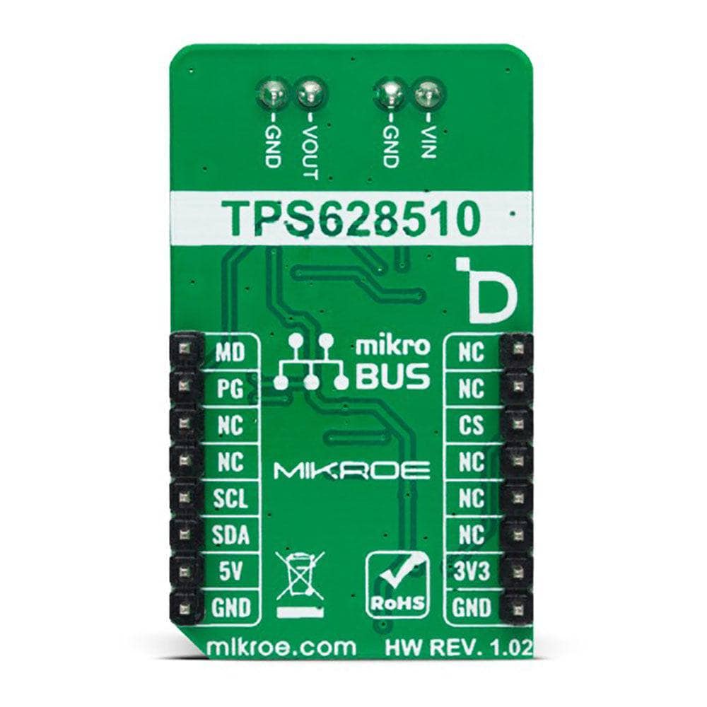
This table shows how the pinout of the Step Down 5 Click Board™ corresponds to the pinout on the mikroBUS™ socket (the latter shown in the two middle columns).
Notes | Pin | Pin | Notes | ||||
---|---|---|---|---|---|---|---|
NC | 1 | AN | PWM | 16 | MD | Mode Selection | |
NC | 2 | RST | INT | 15 | PG | Power-Good Indicator | |
NC | 3 | CS | RX | 14 | NC | ||
NC | 4 | SCK | TX | 13 | NC | ||
NC | 5 | MISO | SCL | 12 | SCL | I2C Clock | |
NC | 6 | MOSI | SDA | 11 | SDA | I2C Data | |
Power Supply | 3.3V | 7 | 3.3V | 5V | 10 | 5V | Power Supply |
Ground | GND | 8 | GND | GND | 9 | GND | Ground |
ONBOARD SETTINGS AND INDICATORS
Label | Name | Default | Description |
---|---|---|---|
LD1 | PWR | - | Power LED Indicator |
JP1 | VCC SEL | Left | Logic Level Voltage Selection 3V3/5V: Left position 3V3, Right position 5V |
JP2-JP4 | ADDR SEL | Left | I2C Address Selection 0/1: Left position 0, Right position 1 |
STEP DOWN 5 CLICK ELECTRICAL SPECIFICATIONS
Description | Min | Typ | Max | Unit |
---|---|---|---|---|
Supply Voltage | 3.3 | - | 5 | V |
External Supply Voltage | 2.7 | - | 6 | V |
Output Voltage | 0.6 | - | 5.5 | V |
Output Current | - | - | 0.5 | A |
Software Support
Software Support
We provide a library for the Step Down 5 Click Board™ as well as a demo application (example), developed using MikroE compilers. The demo can run on all the main MikroE development boards.
The package can be downloaded/installed directly from NECTO Studio. The package Manager (recommended), is from our LibStock™ or found on MikroE Github account.
Library Description
This library contains API for Step Down 5 Click driver.
Key functions
-
stepdown5_set_wiper_0_pos
Step Down 5 set wiper 0 position. -
stepdown5_set_r1_resistance
Step Down 5 set potentiometer 0 resistance. -
stepdown5_set_output
Step Down 5 set output voltage.
Example Description
This library contains API for the Step Down 5 Click Board™ driver. This driver provides the functions to set the output voltage threshold.
void application_task ( void )
{
for ( uint8_t n_cnt = STEPDOWN5_OUTPUT_0V6; n_cnt <= STEPDOWN5_OUTPUT_3V3; n_cnt++ )
{
stepdown5_set_output( &stepdown5, n_cnt );
log_printf( &logger, " Selected output is:" );
print_selected_output_level ( n_cnt );
Delay_ms( 5000 );
}
}
The full application code, and ready to use projects can be installed directly from NECTO Studio The package Manager (recommended), downloaded from our LibStock™ or found on MikroE Github account.
Other MikroE Libraries used in the example:
- MikroSDK.Board
- MikroSDK.Log
- Click.StepDown5
Additional Notes and Information
Depending on the development board you are using, you may need USB UART Click Board™, USB UART 2 Click or RS232 Click to connect to your PC, for development systems with no UART to USB interface available on the board. UART terminal is available in all MikroE compilers.
MIKROSDK
The Step Down 5 Click Board™ is supported with mikroSDK - MikroE Software Development Kit, that needs to be downloaded from the LibStock and installed for the compiler you are using to ensure proper operation of mikroSDK compliant Click board™ demo applications.
Software Support
Software Support
We provide a library for the Step Down 5 Click Board™ as well as a demo application (example), developed using MikroE compilers. The demo can run on all the main MikroE development boards.
The package can be downloaded/installed directly from NECTO Studio. The package Manager (recommended), is from our LibStock™ or found on MikroE Github account.
Library Description
This library contains API for Step Down 5 Click driver.
Key functions
-
stepdown5_set_wiper_0_pos
Step Down 5 set wiper 0 position. -
stepdown5_set_r1_resistance
Step Down 5 set potentiometer 0 resistance. -
stepdown5_set_output
Step Down 5 set output voltage.
Example Description
This library contains API for the Step Down 5 Click Board™ driver. This driver provides the functions to set the output voltage threshold.
void application_task ( void )
{
for ( uint8_t n_cnt = STEPDOWN5_OUTPUT_0V6; n_cnt <= STEPDOWN5_OUTPUT_3V3; n_cnt++ )
{
stepdown5_set_output( &stepdown5, n_cnt );
log_printf( &logger, " Selected output is:" );
print_selected_output_level ( n_cnt );
Delay_ms( 5000 );
}
}
The full application code, and ready to use projects can be installed directly from NECTO Studio The package Manager (recommended), downloaded from our LibStock™ or found on MikroE Github account.
Other MikroE Libraries used in the example:
- MikroSDK.Board
- MikroSDK.Log
- Click.StepDown5
Additional Notes and Information
Depending on the development board you are using, you may need USB UART Click Board™, USB UART 2 Click or RS232 Click to connect to your PC, for development systems with no UART to USB interface available on the board. UART terminal is available in all MikroE compilers.
MIKROSDK
The Step Down 5 Click Board™ is supported with mikroSDK - MikroE Software Development Kit, that needs to be downloaded from the LibStock and installed for the compiler you are using to ensure proper operation of mikroSDK compliant Click board™ demo applications.
Étape 5 Cliquez sur le tableau
Frequently Asked Questions
Ask a Question-
What software development support is available for the Step Down 5 Click Board™?
The Step Down 5 Click Board™ is supported by a mikroSDK-compliant library, which includes functions that simplify software development.
-
What applications is the Step Down 5 Click Board™ suitable for?
The Step Down 5 Click Board™ is suitable for power conversion solutions in various applications, including automation and control, industrial sensors, test and measurement equipment, and portable low-power devices.
-
What are the features of the Step Down 5 Click Board™?
The Step Down 5 Click Board™ has several features, including: 1) The ability to convert higher voltages into lower voltages 2) A TPS628510 DC/DC converter 3) The ability to provide up to 500mA output current 4) Input voltage ranging from 2.7V to 6V 5) Fixed switching frequency of 2.25MHz 6) Selectable output voltage from 0.6V to 5.5V 7) Power Good signal to indicate stabilized output voltage
-
What is the TPS628510?
The TPS628510 is a DC/DC converter from Texas Instruments that can provide up to 500mA output current with an input voltage ranging from 2.7V to 6V. It is specifically designed for applications where high efficiency is crucial and has a switching frequency of 2.25MHz.
-
What is the Step Down 5 Click Board™?
The Step Down 5 Click Board™ is an add-on board that can convert a higher voltage into a lower voltage level. It features the TPS628510, a high-efficiency, easy-to-use, synchronous step-down DC/DC converter from Texas Instruments.