


Mikroelektronika d.o.o.
Tableau de clic Accel 21
Tableau de clic Accel 21
Impossible de charger la disponibilité du service de retrait
Key Features:
- Capteur MEMS hautes performances avec traitement du signal sur puce, faible consommation d'énergie, interruptions programmables, interface sélectionnable, détection d'orientation 6D/4D, détection de mouvement et de chute libre, et plus encore
- Basé sur le MIS2DH - capteur d'accélération triaxial numérique de STMicroelectronics
- Peut être utilisé pour de multiples applications telles que les fonctions activées par le mouvement, la détection de posture et de chute libre, etc.
- mikroBUS : interfaces I2C et SPI
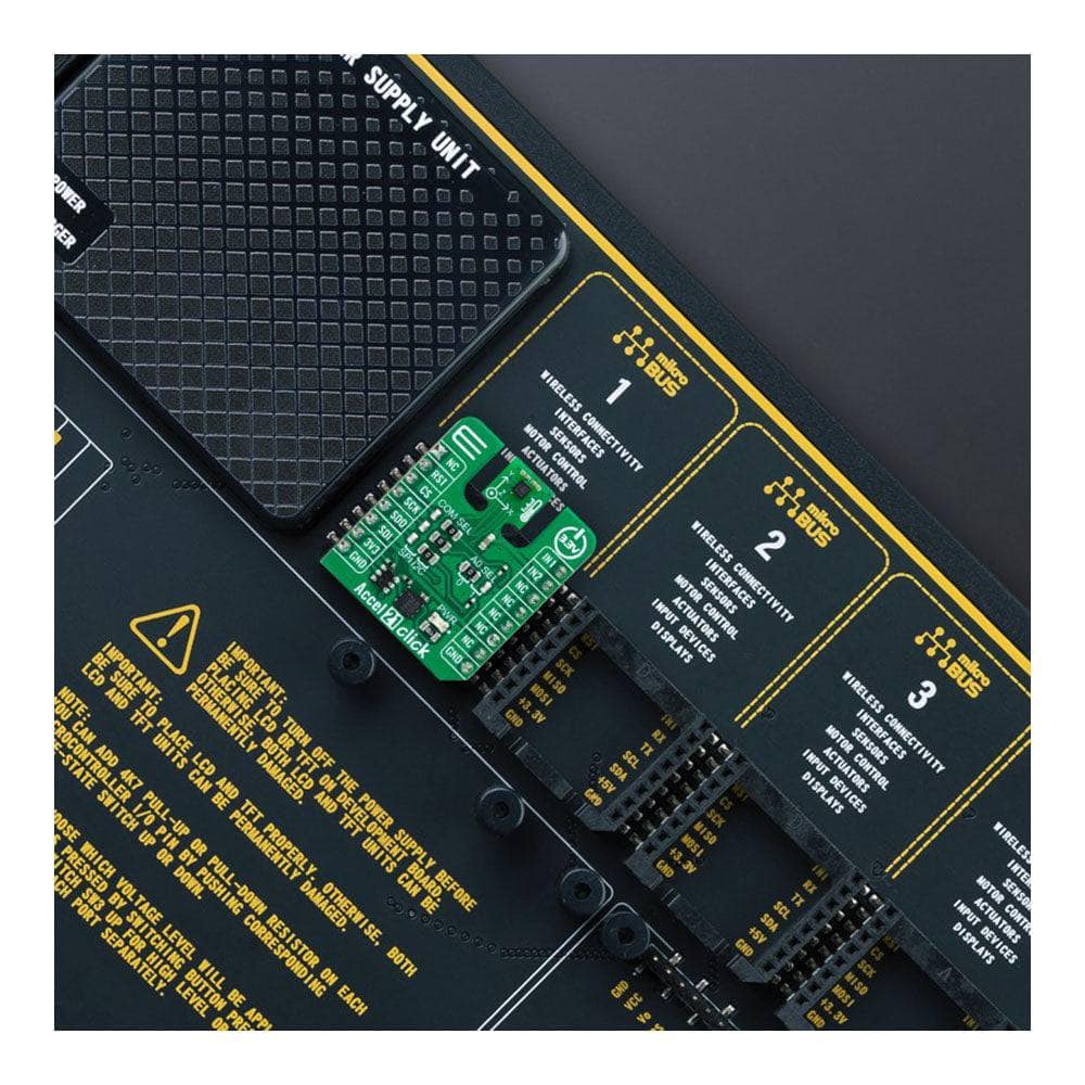
Découvrez des possibilités illimitées avec l' Accel 21 Click Board™ ! Procurez-vous la carte d'extension compacte qui en met plein la vue avec son accéléromètre à trois axes hautes performances de STMicroelectronics. Le capteur MIS2DH permet des mesures d'accélération à pleine échelle sélectionnables dans des plages de ±2g, ±4g, ±8g ou ±16g sur trois axes et dispose d'une interface hôte configurable pour les communications série SPI et I2C. Bénéficiez d'une flexibilité maximale avec ses modes de fonctionnement haute résolution et basse consommation, parfaits pour les fonctions activées par le mouvement, la détection de posture et de chute libre, et bien plus encore !
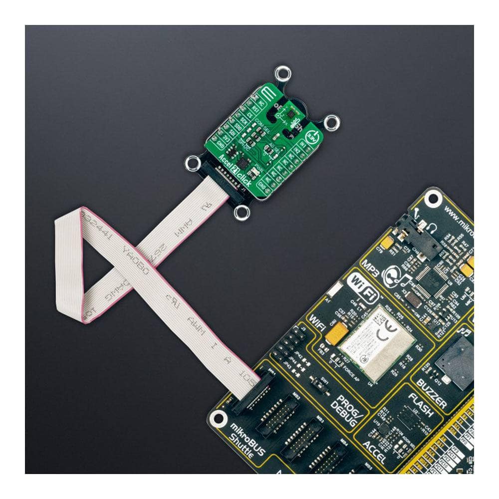
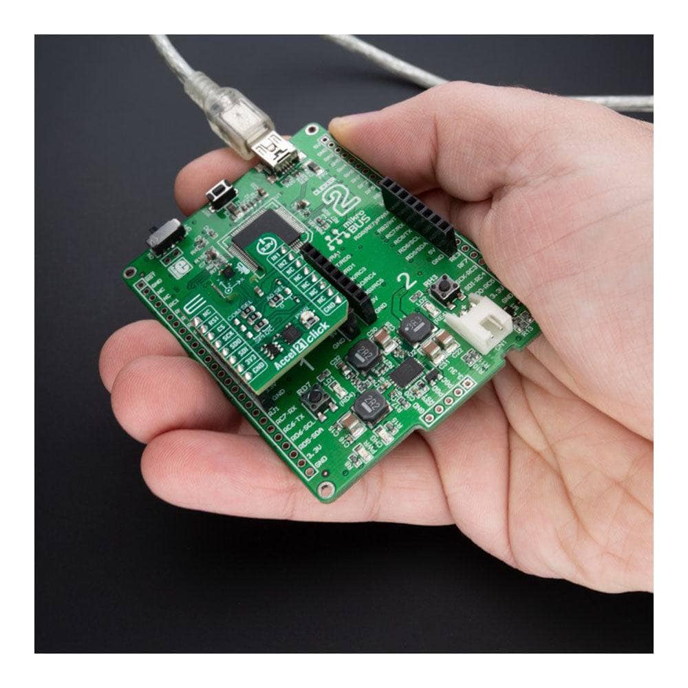
Facilitez le développement de logiciels grâce à la prise en charge de la bibliothèque compatible mikroSDK par l'Accel 21 Click Board™ et à sa conception entièrement testée et prête à l'emploi pour les systèmes équipés du socket mikroBUS™. Procurez-vous dès aujourd'hui ce produit révolutionnaire !
How Does The Accel 21 Click Board™ Work?
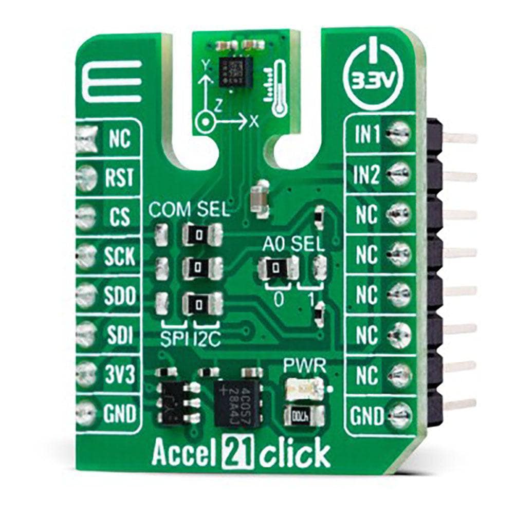
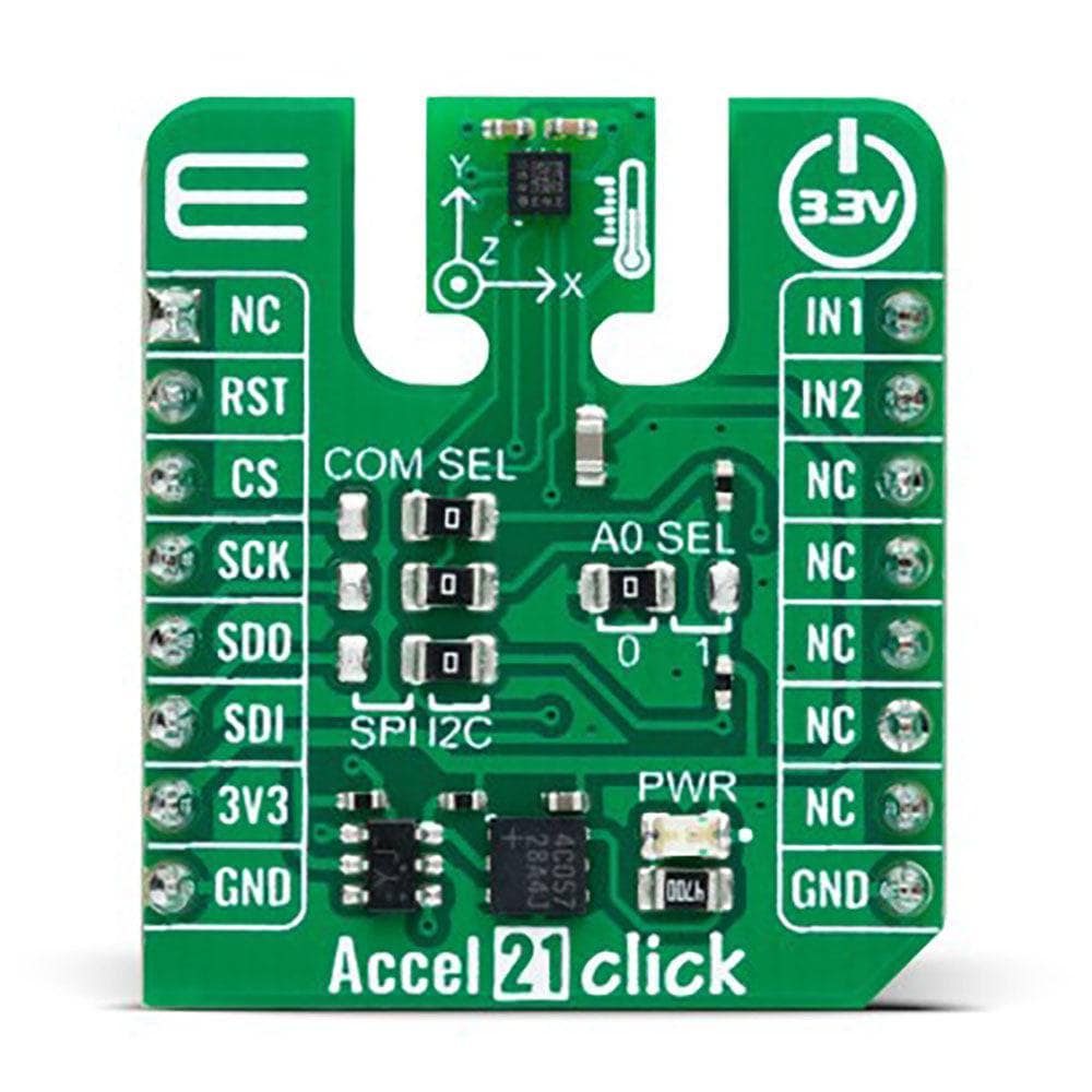
The Accel 21 Click Board™ is based on the MIS2DH, a highly reliable digital triaxial acceleration and temperature sensor from STMicroelectronics. The MIS2DH is highly configurable with a programmable acceleration range of ±2g, ±4g, ±8g, or ±16g, capable of measuring accelerations with output data rates from 1Hz to 5.3kHz. Multiple operating modes (high-resolution, normal, and low-power mode) with various bandwidths and output data resolutions contribute significantly to applications such as activity monitoring and posture detection.
The complete measurement chain is composed of a low-noise capacitive amplifier which converts the capacitive unbalance of the MEMS sensor into an analogue voltage that will be available to the user through an analogue-to-digital converter. The acceleration data is accessed through I2C or SPI interface with a maximum frequency of 400kHz for I2C and 10MHz for SPI communication. The selection is made by positioning SMD jumpers labelled COMM SEL in an appropriate position. Note that all the jumpers' positions must be on the same side, or the Click board™ may become unresponsive. While the I2C interface is selected, the MIS2DH allows choosing the least significant bit (LSB) of its I2C slave address using the SMD jumper labelled ADDR SEL.
The MIS2DH also possesses two interrupts, IN1 and IN2, routed to the PWM and INT pins on the mikroBUS™ socket, entirely programmed by the user through a serial interface. They signal MCU that an event, such as inertial wake-up/free-fall or the board's position, has been sensed.
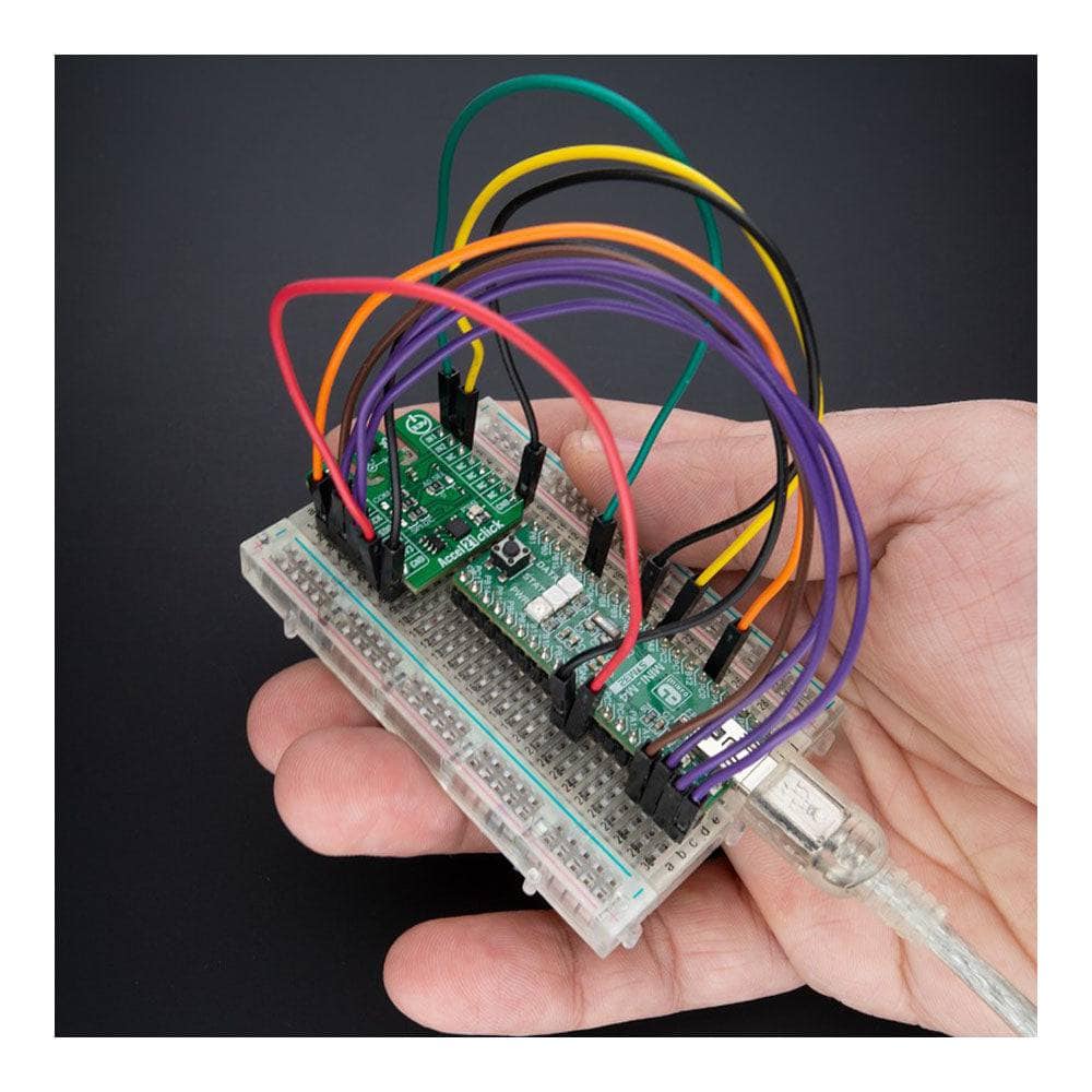
The Accel 21 Click Board™ can only operate with a 3.3V logic voltage level. The board must perform appropriate logic voltage level conversion before using MCUs with different logic levels. However, the Click board™ comes equipped with a library containing functions and an example code that can be used as a reference for further development.
SPECIFICATIONS
| Type | Motion |
| Applications | It can be used for multiple applications such as motion-activated functions, posture and free-fall detection, and more |
| On-board modules | MIS2DH - digital triaxial acceleration sensor from STMicroelectronics |
| Key Features | High performance, MEMS sensor with on-chip signal processing, low power consumption, programmable interrupts, selectable interface, 6D/4D orientation detection, motion and free-fall detection, and more |
| Interface | I2C,SPI |
| Compatibility | mikroBUS |
| Click board size | S (28.6 x 25.4 mm) |
| Input Voltage | 3.3V |
PINOUT DIAGRAM
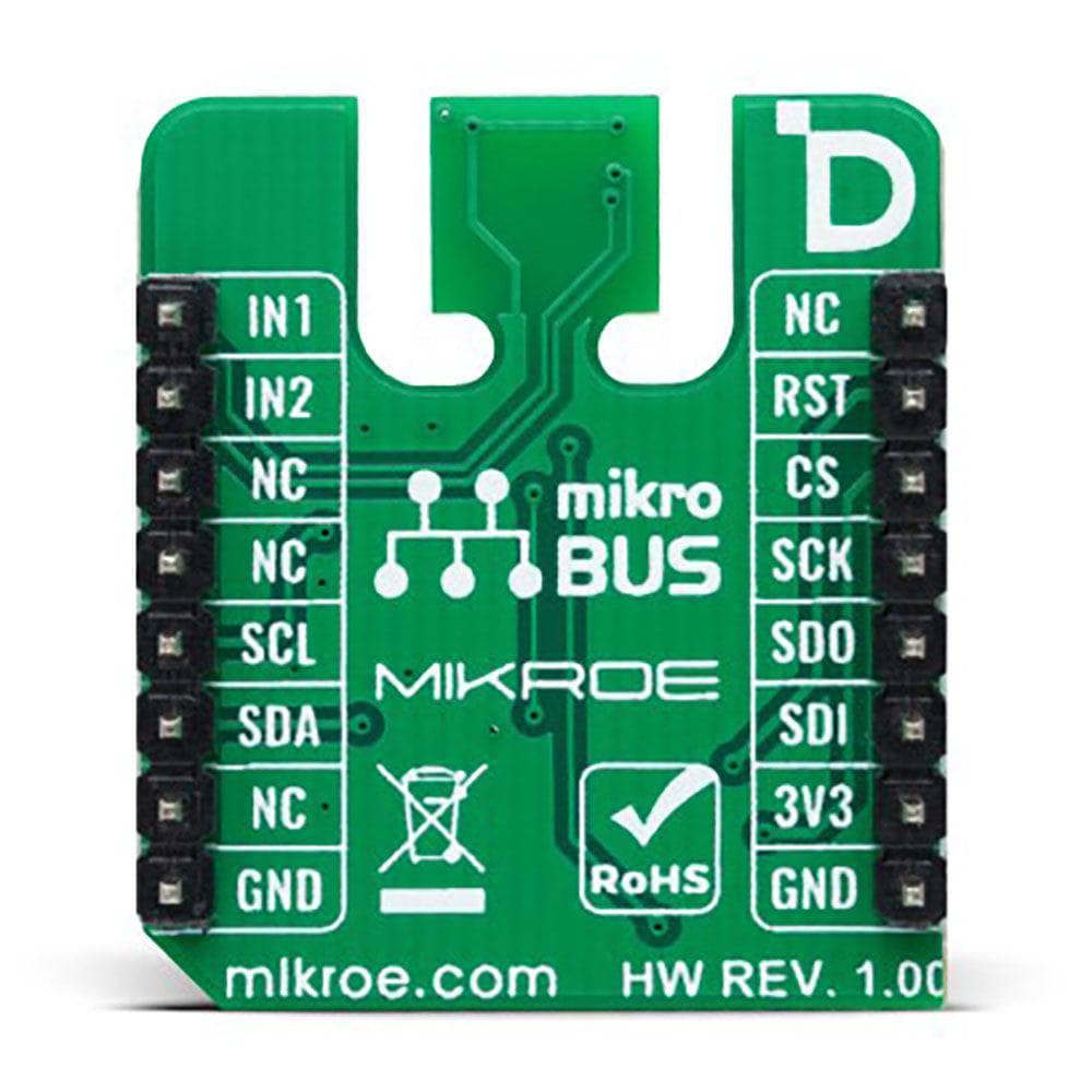
This table shows how the pinout of the Accel 21 Click Board™ corresponds to the pinout on the mikroBUS™ socket (the latter shown in the two middle columns).
| Notes | Pin | Pin | Notes | ||||
|---|---|---|---|---|---|---|---|
| NC | 1 | AN | PWM | 16 | IN1 | Interrupt 1 | |
| NC | 2 | RST | INT | 15 | IN2 | Interrupt 2 | |
| SPI Chip Select | CS | 3 | CS | RX | 14 | NC | |
| SPI Clock | SCK | 4 | SCK | TX | 13 | NC | |
| SPI Data OUT | SDO | 5 | MISO | SCL | 12 | SCL | I2C Clock |
| SPI Data IN | SDI | 6 | MOSI | SDA | 11 | SDA | I2C Data |
| Power Supply | 3.3V | 7 | 3.3V | 5V | 10 | NC | |
| Ground | GND | 8 | GND | GND | 9 | GND | Ground |
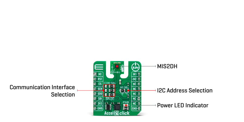
ONBOARD SETTINGS AND INDICATORS
| Label | Name | Default | Description |
|---|---|---|---|
| LD1 | PWR | - | Power LED Indicator |
| JP1 | ADDR SEL | Left | I2C Address Selection 0/1: Left position 0, Right position 1 |
| JP2-JP4 | COMM SEL | Right | Communication Interface Selection SPI/I2C: Left position SPI, Right position I2C |
ACCEL 21 CLICK ELECTRICAL SPECIFICATIONS
| Description | Min | Typ | Max | Unit |
|---|---|---|---|---|
| Supply Voltage | - | 3.3 | - | V |
| Acceleration Range | ±2 | - | ±16 | g |
| Acceleration Resolution | 8 | 10 | 12 | bits |
| Sensitivity (±2 ~ ±16) | 3.91 | - | 188.68 | mg/digit |
Software Support
We provide a library for the Accel 21 Click Board™ as well as a demo application (example), developed using MikroE compilers. The demo can run on all the main MikroE development boards.
The package can be downloaded/installed directly from NECTO Studio The package Manager (recommended), downloaded from our LibStock™ or found on MikroE Github account.
Library Description
This library contains API for the Accel 21 Click Board™ driver.
Key functions
-
accel21_set_configAccel 21 set config function. -
accel21_get_axisAccel 21 get accel data function. -
accel21_get_temperatureAccel 21 get temperature function.
Example Description
This library contains API for the Accel 21 Click Board™ driver. The library initializes and defines the I2C or SPI bus drivers to write and read data from registers. The library also includes a function for reading X-axis, Y-axis, and Z-axis data.
void application_task ( void )
 {
     static accel21_axis_t axis;
     accel21_get_axis( &accel21, &axis );
     log_printf( &logger, "tX : %d rntY : %d rntZ : %d rn", axis.x, axis.y, axis.z );
     log_printf( &logger, "------------------------rn" );
     Delay_ms( 1000 );
 }
The full application code, and ready to use projects can be installed directly from NECTO Studio The package Manager (recommended), downloaded from our LibStock™ or found on MikroE Github account.
Other MikroE Libraries used in the example:
- MikroSDK.Board
- MikroSDK.Log
- Click.Accel21
Additional Notes and Information
Depending on the development board you are using, you may need USB UART Click Board™, USB UART 2 Click or RS232 Click to connect to your PC, for development systems with no UART to USB interface available on the board. UART terminal is available in all MikroE compilers.
MIKROSDK
The Accel 21 Click Board™ is supported with mikroSDK - MikroE Software Development Kit. To ensure proper operation of mikroSDK compliant Click board™ demo applications, mikroSDK should be downloaded from the LibStock and installed for the compiler you are using.
Tableau de clic Accel 21
Frequently Asked Questions
Have a Question?
Be the first to ask a question about this.