


Mikroelektronika d.o.o.
Tableau de clic Accel 27
Tableau de clic Accel 27
Impossible de charger la disponibilité du service de retrait
Key Features:
- Plage de mesure ±400g, bande passante sélectionnable par l'utilisateur avec filtre anti-crénelage à 4 pôles, rapport de suréchantillonnage sélectionnable, faible consommation d'énergie, fonctionnalités intégrées pour les économies d'énergie du système, interface sélectionnable, surveillance des événements, etc.
- Basé sur l'ADXL373 - accéléromètre MEMS à trois axes d'Analog Devices
- Peut être utilisé pour les fonctions activées par le mouvement, la détection d'impact et de choc, les applications IoT médicales, etc.
- mikroBUS : interfaces I2C et SPI
Présentation de l'Accel 27 Click Board™
L'Accel 27 Click Board™ est une carte complémentaire compacte qui contient un capteur d'accélération, parfait pour vos besoins de détection de mouvement. Avec l'ADXL373, un accéléromètre MEMS ±400g à trois axes d'Analog Devices, cette carte offre une sensibilité et une précision inégalées dans un format compact.
Caractéristiques
- Consommation d'énergie ultra-faible
- Capacités de détection d'impact
- Données de sortie 12 bits à un facteur d'échelle de 200 mg/LSB
- Interface hôte configurable avec prise en charge de la communication série SPI et I2C
- Prise en charge par une bibliothèque compatible mikroSDK pour un développement logiciel facile
Applications
L'Accel 27 Click Board™ est parfait pour une variété d'applications, notamment :
- Fonctions activées par le mouvement
- Détection d'impact et de choc
- Applications IoT médicales nécessitant une très faible consommation d'énergie pour le réveil par mouvement
- Et plus encore !
Prêt à l'emploi
Cette carte Click™ est un produit entièrement testé, prêt à être utilisé sur un système équipé du socket mikroBUS™. De plus, avec la bibliothèque compatible mikroSDK, le développement de logiciels n'a jamais été aussi simple.
Procurez-vous l'Accel 27 Click Board™ et portez vos capacités de détection de mouvement au niveau supérieur.


How Does The Accel 27 Click Board™ Work?
The Accel 27 Click Board™ is based on the ADXL373, a complete three-axis ±400g acceleration measurement system from Analog Devices, operating at extremely low power levels. Built-in digital logic enables autonomous operation and implements functions that enhance system-level power savings. It offers 12-bit output data at 200mg/LSB scale factor, where acceleration is reported digitally through a configurable and selectable serial interface. The ADXL373 has three operating modes. Measurement mode is used for continuous, broad bandwidth sensing. The wake-up mode is used for limited bandwidth low g activity detection, and the instant-on mode is used for low power impact detection. Measurement can be suspended entirely by placing the ADXL373 in Standby mode.
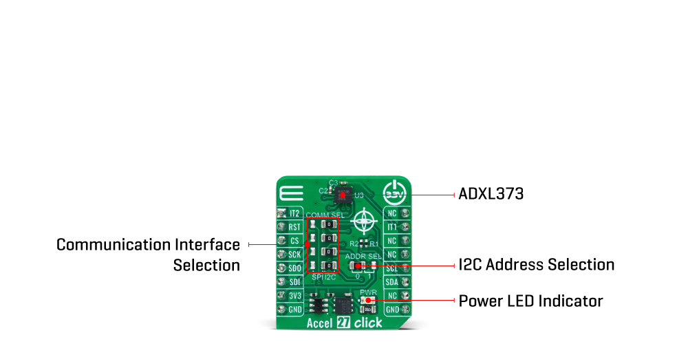
As mentioned, the acceleration data is accessed through I2C or SPI interface with a maximum frequency of 3.4MHz for I2C and 10MHz for SPI communication. The selection is made by positioning SMD jumpers labelled COMM SEL in an appropriate position. Note that all the jumpers' positions must be on the same side, or the Click board™ may become unresponsive. While the I2C interface is selected, the ADXL373 allows choosing the least significant bit (LSB) of its I2C slave address using the SMD jumper labelled ADDR SEL.
This board also possesses two interrupts, IT1 and IT2, routed to, where by default, the INT and AN pins stand on the mikroBUS™ socket, entirely programmed by the user through a serial interface. They signal MCU that a motion event has been sensed.
The Accel 27 Click Board™ can be operated only with a 3.3V logic voltage level. The board must perform appropriate logic voltage level conversion before using MCUs with different logic levels. However, the Click board™ comes equipped with a library containing functions and an example code that can be used as a reference for further development.
SPECIFICATIONS
| Type | Motion |
| Applications | It can be used for motion-activated functions, impact, and shock detection, medical IoT applications, and more |
| On-board modules | ADXL373 - three-axis MEMS accelerometer from Analog Devices |
| Key Features | ±400g measurement range, user-selectable bandwidth with 4-pole antialiasing filter, selectable oversampling ratio, low power consumption, built-in features for system power savings, selectable interface, event monitoring, and more |
| Interface | I2C,SPI |
| Compatibility | mikroBUS |
| Input Voltage | 3.3V |
PINOUT DIAGRAM
This table shows how the pinout of the Accel 27 Click Board™ corresponds to the pinout on the mikroBUS™ socket (the latter shown in the two middle columns).
| Notes | Pin | Pin | Notes | ||||
|---|---|---|---|---|---|---|---|
| Interrupt 2 | IT2 | 1 | AN | PWM | 16 | NC | |
| NC | 2 | RST | INT | 15 | IT1 | Interrupt 1 | |
| SPI Chip Select | CS | 3 | CS | RX | 14 | NC | |
| SPI Clock | SCK | 4 | SCK | TX | 13 | NC | |
| SPI Data OUT | SDO | 5 | MISO | SCL | 12 | SCL | I2C Clock |
| SPI Data IN | SDI | 6 | MOSI | SDA | 11 | SDA | I2C Data |
| Power Supply | 3.3V | 7 | 3.3V | 5V | 10 | NC | |
| Ground | GND | 8 | GND | GND | 9 | GND | Ground |
ONBOARD SETTINGS AND INDICATORS
| Label | Name | Default | Description |
|---|---|---|---|
| LD1 | PWR | - | Power LED Indicator |
| JP1-JP4 | COMM SEL | Right | Communication Interface Selection SPI/I2C: Left position SPI, Right position I2C |
| JP5 | ADDR SEL | Left | I2C Address Selection 0/1: Left position 0, Right position 1 |
ACCEL 27 CLICK ELECTRICAL SPECIFICATIONS
| Description | Min | Typ | Max | Unit |
|---|---|---|---|---|
| Supply Voltage | - | 3.3 | - | V |
| Acceleration Range | - | ±400 | - | g |
| Resolution | - | 12 | - | bits |
| Scale Factor | - | 200 | - | mg/LSB |
Software Support
We provide a library for the Accel 27 Click as well as a demo application (example), developed using MikroE compilers. The demo can run on all the main MikroE development boards.
The package can be downloaded/installed directly from NECTO Studio The package Manager (recommended), downloaded from our LibStock™ or found on MikroE Github account.
Library Description
This library contains API for the Accel 27 Click Board™ driver.
Key functions
-
accel27_get_int1_pinThis function returns the interrupt 1 (INT1) pin logic state. -
accel27_get_axesThis function reads accel X, Y, and Z axis data in g. -
accel27_reset_deviceThis function performs the chip software reset.
Example Description
This example demonstrates the use of the Accel 27 Click Board™ by reading and displaying the accelerometer data (X, Y, and Z axis) averaged from 100 samples.
void application_task ( void )
 {
     accel27_axes_t axes = { 0 };
     uint16_t cnt = 0;
     while ( cnt < NUM_OF_SAMPLES )
     {
         // Wait for data ready indication
         while ( !accel27_get_int1_pin ( &accel27 ) );

         accel27_axes_t tmp_axes;
         if ( ACCEL27_OK == accel27_get_axes ( &accel27, &tmp_axes ) )
         {
             axes.x += tmp_axes.x;
             axes.y += tmp_axes.y;
             axes.z += tmp_axes.z;
             cnt++;
         }
     }
     axes.x = axes.x / NUM_OF_SAMPLES;
     axes.y = axes.y / NUM_OF_SAMPLES;
     axes.z = axes.z / NUM_OF_SAMPLES;
     log_printf( &logger, " X: %.1f grn", axes.x );
     log_printf( &logger, " Y: %.1f grn", axes.y );
     log_printf( &logger, " Z: %.1f grnn", axes.z );
 }
The full application code, and ready to use projects can be installed directly from NECTO Studio The package Manager (recommended), downloaded from our LibStock™ or found on MikroE Github account.
Other MikroE Libraries used in the example:
- MikroSDK.Board
- MikroSDK.Log
- Click.Accel27
Additional Notes and Information
Depending on the development board you are using, you may need USB UART Click Board™, USB UART 2 Click or RS232 Click to connect to your PC, for development systems with no UART to USB interface available on the board. UART terminal is available in all MikroE compilers.
MIKROSDK
The Accel 27 Click Board™ is supported with mikroSDK - MikroE Software Development Kit, which needs to be downloaded from the LibStock and installed for the compiler you are using to ensure proper operation of mikroSDK compliant Click board™ demo applications.
Tableau de clic Accel 27
Frequently Asked Questions
Ask a Question-
What is the mikroBUS™ socket?
The mikroBUS™ socket is a standardised socket interface that enables seamless integration of Click boards™ with compatible development boards or systems.
-
Do I need to assemble or test the Accel 27 Click Board™ before use?
No, the Accel 27 Click Board™ comes as a fully tested product, ready for use on a system equipped with a mikroBUS™ socket.
-
What is the mikroSDK-compliant library?
The mikroSDK-compliant library is a collection of functions that simplifies software development for the Accel 27 Click Board™. It ensures compatibility and easy integration with other supported mikroSDK components.
-
What communication protocols does the Accel 27 Click Board™ support?
The board supports both SPI (Serial Peripheral Interface) and I2C (Inter-Integrated Circuit) serial communication protocols via its configurable host interface.
-
What is the ADXL373 accelerometer?
The ADXL373 is a three-axis MEMS ±400g accelerometer from Analog Devices. It provides 12-bit output data at a 200mg/LSB scale factor and has ultra-low power consumption.
-
What applications can the Accel 27 Click Board™ be used for?
This board is suitable for various applications such as motion-activated functions, impact and shock detection, medical IoT applications requiring ultra-low-power Wake-Up on motion, and more.
-
What is the Accel 27 Click Board™?
The Accel 27 Click Board™ is a compact add-on board featuring the ADXL373, a three-axis MEMS ±400g accelerometer from Analog Devices. It is designed to enable impact detection and provide system-level power reduction, making it suitable for a range of applications.