Key Features
Overview
Introducing the DC Motor 25 Click Board™ - The Ultimate Brushed DC Motor Driver!
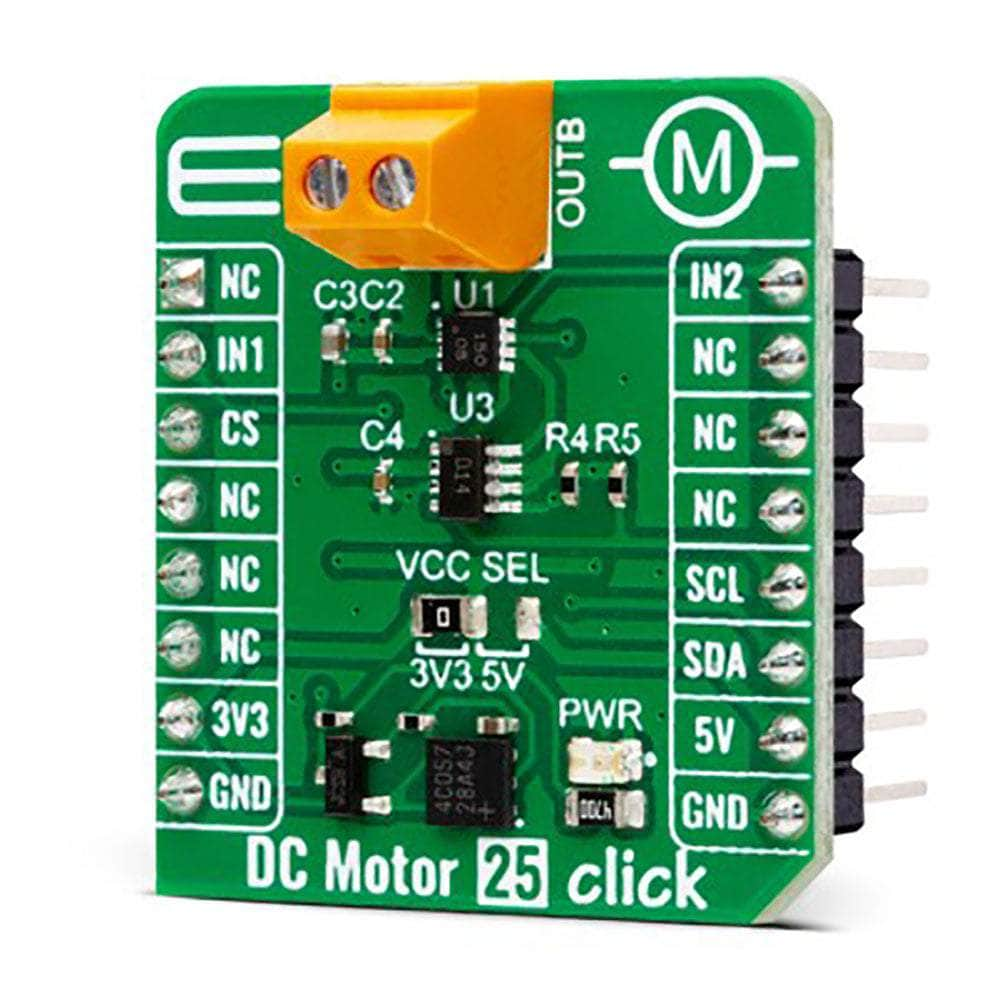
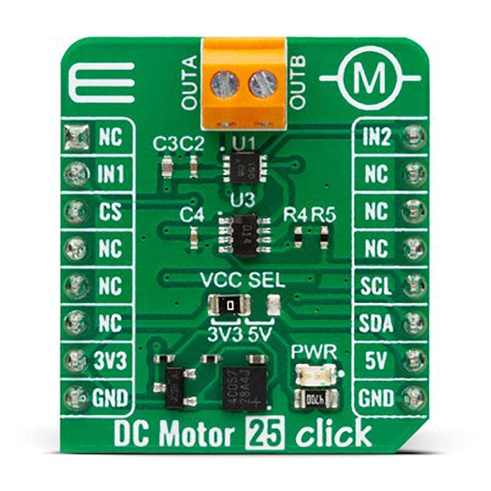
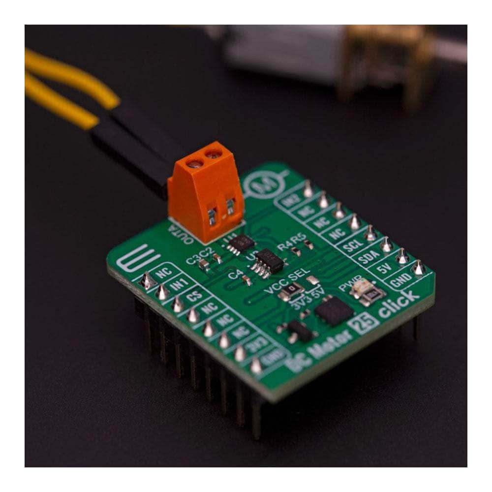
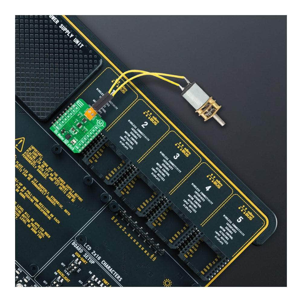
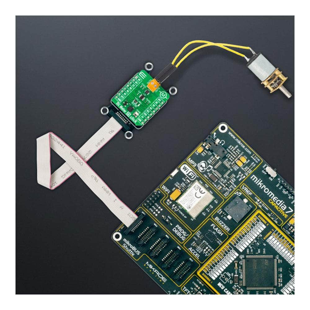
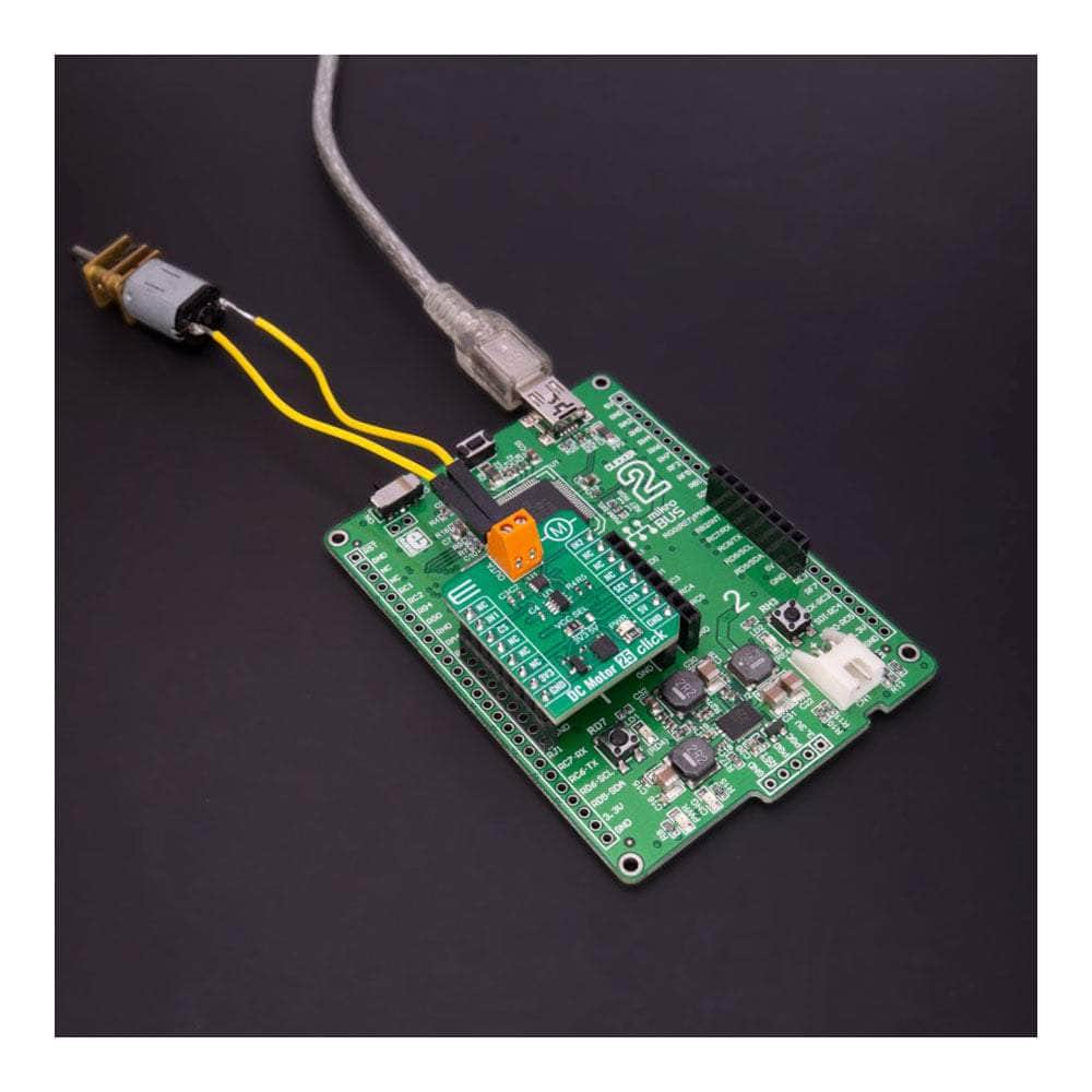
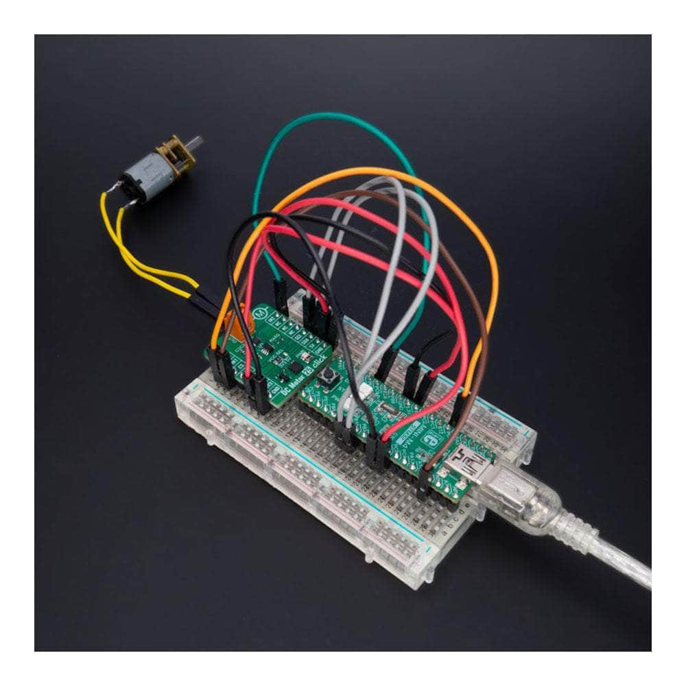
Unlock the full potential of your brushed DC motors with the all-new DC Motor 25 Click Board™! This compact add-on board is designed to deliver outstanding performance and versatility, thanks to the cutting-edge A3908 low-voltage bidirectional DC motor driver from Allegro Microsystems.
Experience Unparalleled Power and Efficiency
With an operating voltage range fully compatible with mikroBUS™ power rails and able to handle output currents of up to 500mA, the DC Motor 25 Click Board™ is perfect for a wide range of applications. Its unique output full-bridge incorporates source-side linear operation, ensuring a constant voltage across the motor coil for maximum efficiency.
Enjoy Ultimate Control and Flexibility
Logic input pins are at your disposal for precise control over the motor's direction of rotation, brake, and standby modes. This means you can easily fine-tune your device's performance to fit your specific needs, whether it's robotic actuators, pumps, battery-powered toys and games, low-noise instrumentation systems, or any other application that requires a reliable DC motor driver.
Stay Protected with Complete Protection Capabilities
The DC Motor 25 Click Board™ comes equipped with comprehensive protection features, ensuring robust and reliable operation in even the most demanding environments. Keep your devices running smoothly and safely, no matter the challenge.
Effortless Software Development with mikroSDK
Thanks to its mikroSDK-compliant library, the DC Motor 25 Click Board™ streamlines software development by providing you with various helpful functions. This means you can spend less time coding and more time enjoying your newly enhanced devices!
Plug and Play for a Seamless Experience
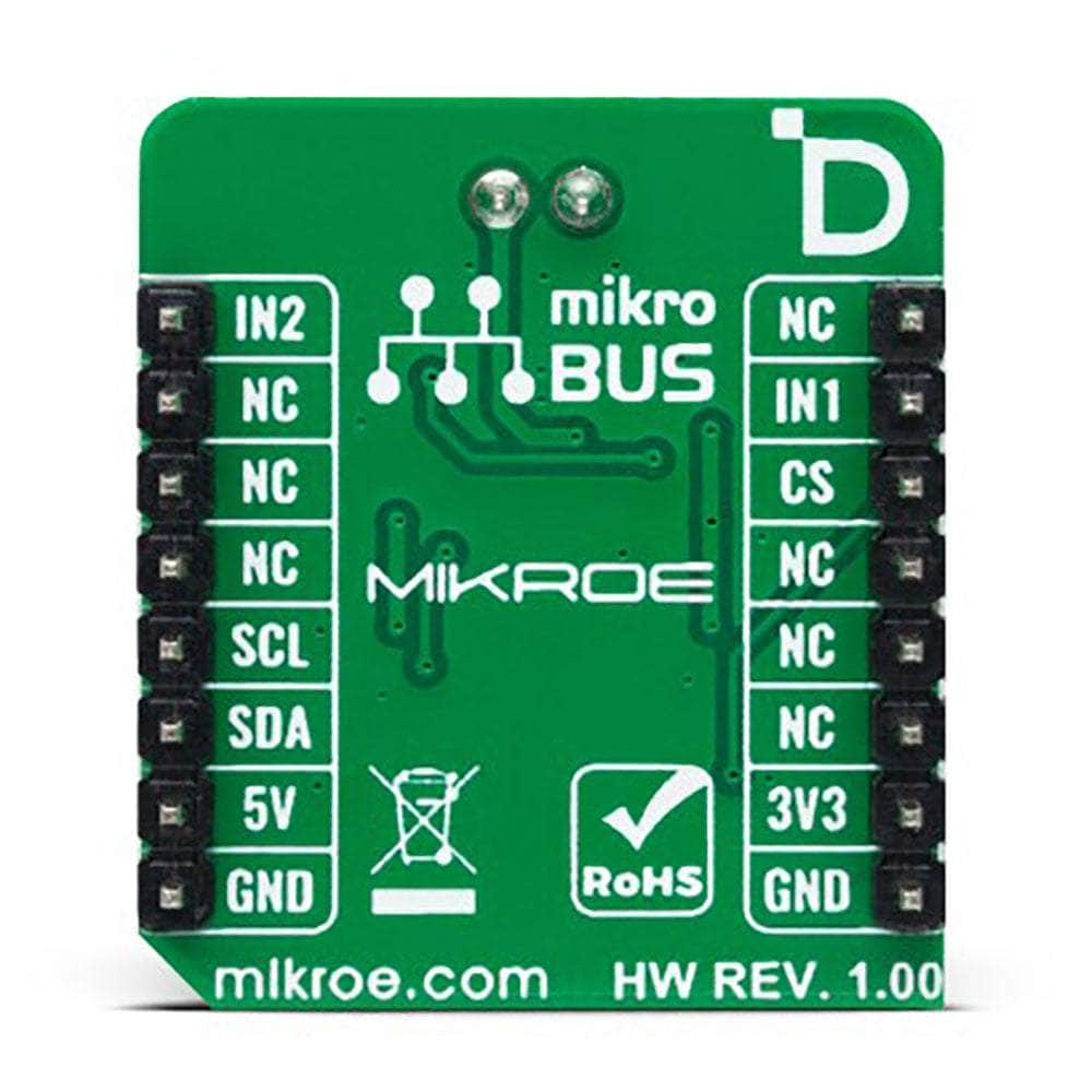
Designed for immediate use on a system equipped with a mikroBUS™ socket, the DC Motor 25 Click Board™ comes as a fully tested product. Get ready to experience the future of brushed DC motor drivers today!
Downloads
Présentation du DC Motor 25 Click Board™ - Le pilote de moteur à courant continu à balais ultime !
Libérez tout le potentiel de vos moteurs à courant continu à balais avec la toute nouvelle carte DC Motor 25 Click Board™ ! Cette carte complémentaire compacte est conçue pour offrir des performances et une polyvalence exceptionnelles, grâce au pilote de moteur à courant continu bidirectionnel basse tension A3908 de pointe d'Allegro Microsystems.
Découvrez une puissance et une efficacité inégalées
Avec une plage de tension de fonctionnement entièrement compatible avec les rails d'alimentation mikroBUS™ et capable de gérer des courants de sortie allant jusqu'à 500 mA, le DC Motor 25 Click Board™ est parfait pour une large gamme d'applications. Son pont complet de sortie unique intègre un fonctionnement linéaire côté source, garantissant une tension constante sur la bobine du moteur pour une efficacité maximale.
Bénéficiez d'un contrôle et d'une flexibilité ultimes
Des broches d'entrée logique sont à votre disposition pour un contrôle précis du sens de rotation, du freinage et des modes veille du moteur. Cela signifie que vous pouvez facilement ajuster les performances de votre appareil en fonction de vos besoins spécifiques, qu'il s'agisse d'actionneurs robotisés, de pompes, de jouets et de jeux alimentés par batterie, de systèmes d'instrumentation à faible bruit ou de toute autre application nécessitant un pilote de moteur à courant continu fiable.
Restez protégé grâce à des capacités de protection complètes
Le DC Motor 25 Click Board™ est équipé de fonctions de protection complètes, garantissant un fonctionnement robuste et fiable même dans les environnements les plus exigeants. Assurez le bon fonctionnement et la sécurité de vos appareils, quel que soit le défi.
Développement de logiciels sans effort avec mikroSDK
Grâce à sa bibliothèque compatible mikroSDK, le DC Motor 25 Click Board™ simplifie le développement logiciel en vous fournissant diverses fonctions utiles. Cela signifie que vous pouvez passer moins de temps à coder et plus de temps à profiter de vos nouveaux appareils améliorés !
Plug and Play pour une expérience fluide
Conçu pour une utilisation immédiate sur un système équipé d'une prise mikroBUS™, le DC Motor 25 Click Board™ est un produit entièrement testé. Préparez-vous à découvrir dès aujourd'hui l'avenir des pilotes de moteurs à courant continu à balais !
| General Information | |
|---|---|
Part Number (SKU) |
MIKROE-5523
|
Manufacturer |
|
| Physical and Mechanical | |
Weight |
0.02 kg
|
| Other | |
Country of Origin |
|
HS Code Customs Tariff code
|
|
EAN |
8606027384974
|
Warranty |
|
Frequently Asked Questions
Have a Question?
-
Is the DC Motor 25 Click Board™ a tested product?
Yes, the DC Motor 25 Click Board™ comes as a fully tested product, ready for use on a system equipped with the mikroBUS™ socket.
-
What is the mikroBUS™ socket?
The mikroBUS™ socket is a standardized interface that allows you to connect various Click boards™ to a development system. The DC Motor 25 Click Board™ is designed to be used with a system equipped with a mikroBUS™ socket.
-
How can I develop software for the DC Motor 25 Click Board™?
The DC Motor 25 Click Board™ is supported by a mikroSDK-compliant library, which includes functions that simplify software development. You can use these functions to create your software for controlling DC motors easily.
-
What kind of protection capabilities does the DC Motor 25 Click Board™ offer?
The board has complete protection capabilities, including overcurrent protection and thermal protection, ensuring robust and reliable operation.
-
How is the motor direction of rotation controlled?
The DC Motor 25 Click Board™ provides logic input pins to control the motor direction of rotation, brake, and standby modes.
-
What is the maximum output current of the A3908 motor driver?
The A3908 motor driver on the DC Motor 25 Click Board™ can provide output currents up to 500mA.
-
What is the operating voltage range of the A3908 motor driver?
The A3908 motor driver on the DC Motor 25 Click Board™ is rated for an operating voltage range compatible with the mikroBUS™ power rails.
-
What is the DC Motor 25 Click Board™?
The DC Motor 25 Click Board™ is a compact add-on board featuring the A3908 brushed DC motor driver from Allegro Microsystems. It is designed to control brushed DC motors in various applications such as robotic actuators, pumps, battery-powered toys, low-noise instrumentation systems, and more.


