


Mikroelektronika d.o.o.
Carte à clic pour moteur à courant continu 23
Carte à clic pour moteur à courant continu 23
Impossible de charger la disponibilité du service de retrait
Key Features:
- Faible consommation d'énergie, structure basée sur BiCD, tension de claquage élevée/courant important, fonction d'économie d'énergie, diverses fonctions de protection, mode de décroissance sélectionnable, fonction de détection d'erreur, etc.
- Basé sur le TB67H480FNG - pilote de moteur à courant continu à balais à pont en H à double canal de Toshiba Semiconductor
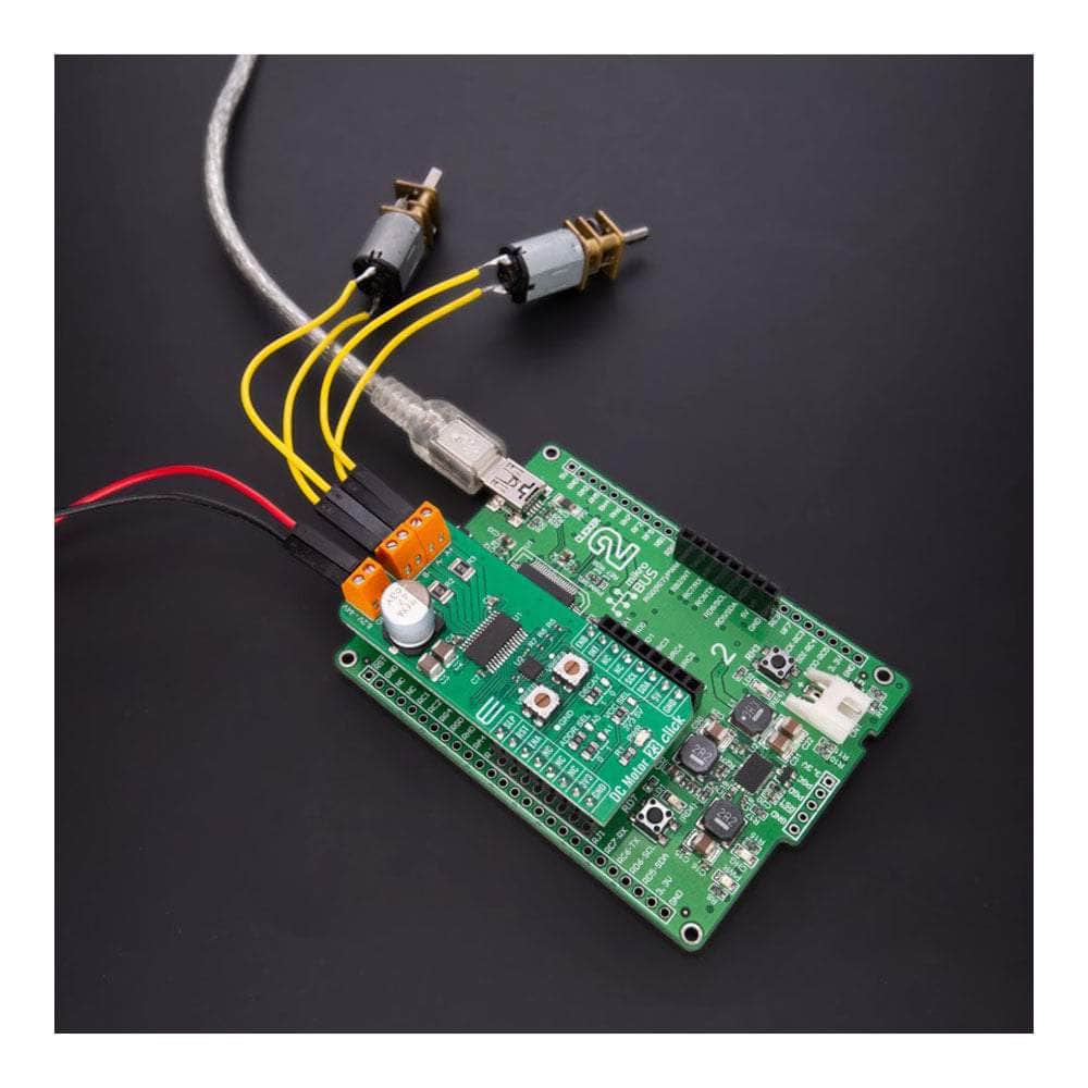
- Peut être utilisé pour piloter deux moteurs à balais ou un moteur pas à pas dans diverses applications telles que l'électronique grand public et les équipements industriels
- mikroBUS : interfaces I2C et GPIO
Libérez la puissance du moteur à courant continu 23 Click Board™
Plongez dans le monde des pilotes de moteurs à courant continu à balais avec notre DC Motor 23 Click Board™ compact et puissant. Cette carte d'extension robuste est équipée du TB67H480FNG, un pilote de moteur à courant continu à balais à pont en H à deux canaux du célèbre Toshiba Semiconductor. Utilisant le processus BiCD de pointe, cette carte garantit un transistor de puissance de sortie impressionnant et offre une large plage de tension de fonctionnement de 8,2 V à 44 V, le tout avec une capacité de courant de sortie maximale de 2 A.
Performances et fiabilité améliorées
Cette carte polyvalente vous offre un éventail de fonctionnalités utiles pour un fonctionnement stable et fiable. Vous apprécierez la fonction de sélection des modes de décroissance, une multitude de fonctions de protection et un indicateur de détection d'anomalie facile à lire. Que vous pilotiez deux moteurs à balais ou un moteur pas à pas, la carte DC Motor 23 Click Board™ est votre solution idéale. Elle s'intègre parfaitement dans une large gamme d'applications, de l'électronique grand public aux équipements industriels.
Intégration et application faciles
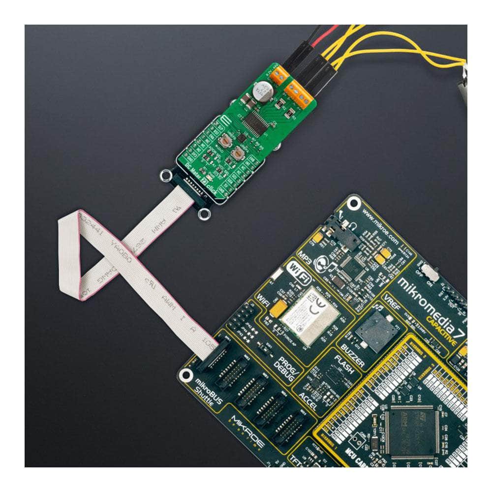
Le DC Motor 23 Click Board™ est fourni avec la prise en charge d'une bibliothèque compatible mikroSDK, simplifiant le développement logiciel et facilitant plus que jamais son intégration dans votre système. De plus, notre Click board™ est livré sous la forme d'un produit entièrement testé, prêt à être intégré de manière transparente dans tout système équipé de la prise mikroBUS™.
How Does The DC Motor 23 Click Board™ Work?
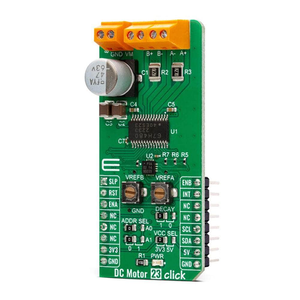
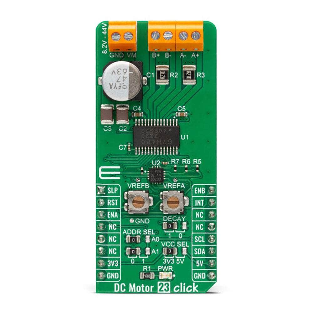
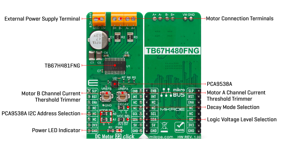
The DC Motor 23 Click Board™ is based on the TB67H480FNG, a dual-channel, H-bridge, brushed DC motor driver from Toshiba Semiconductor. The TB67H480FNG has a current limit function that monitors the current flowing in the motor. When the motor current reaches the set current value, determined using onboard VREF trimmers (VREFA and VREFB), it shifts to Decay mode, selectable by positioning the SMD jumper labelled as DECAY to an appropriate position marked as 0 and 1, for a fixed OFF time and attenuates the current. The TB67H480FNG has a built-in regulator that allows the motor to be driven by a single power supply, provides a motor output voltage rating of around 40V, and has integrated protection mechanisms such as over-current, over-temperature, and under-voltage lockout for error detection.
The setting current value can be adjusted with the torque function (100%, 71%, 38%, or 0%), controlled through the PCA9538A port expander, which establishes communication with the MCU via the I2C serial interface. Lowering the torque setting can suppress the motor current when high torque is not needed. In addition to these torque setting pins, with the help of the expander, it is also possible to control some other signals, such as the control signals for selecting the operating mode of the motor driver. These pins, in combination with ENA and ENB pins, routed to default positions of CS and PWM pins of the mikroBUS™ socket, enable operational modes like CW, CCW, or short-brake.
The PCA9538A also allows choosing the least significant bit (LSB) of its I2C slave address by positioning SMD jumpers labelled as ADDR SEL to an appropriate position marked as 0 and 1, alongside its interrupt feature routed to the INT pin of the mikroBUS™ socket. Besides, all circuits can be stopped using the Sleep function, routed to default positions of the AN pin of the mikroBUS™ socket, and thus enable power saving mode, while the RST pin provides a general-purpose reset function.
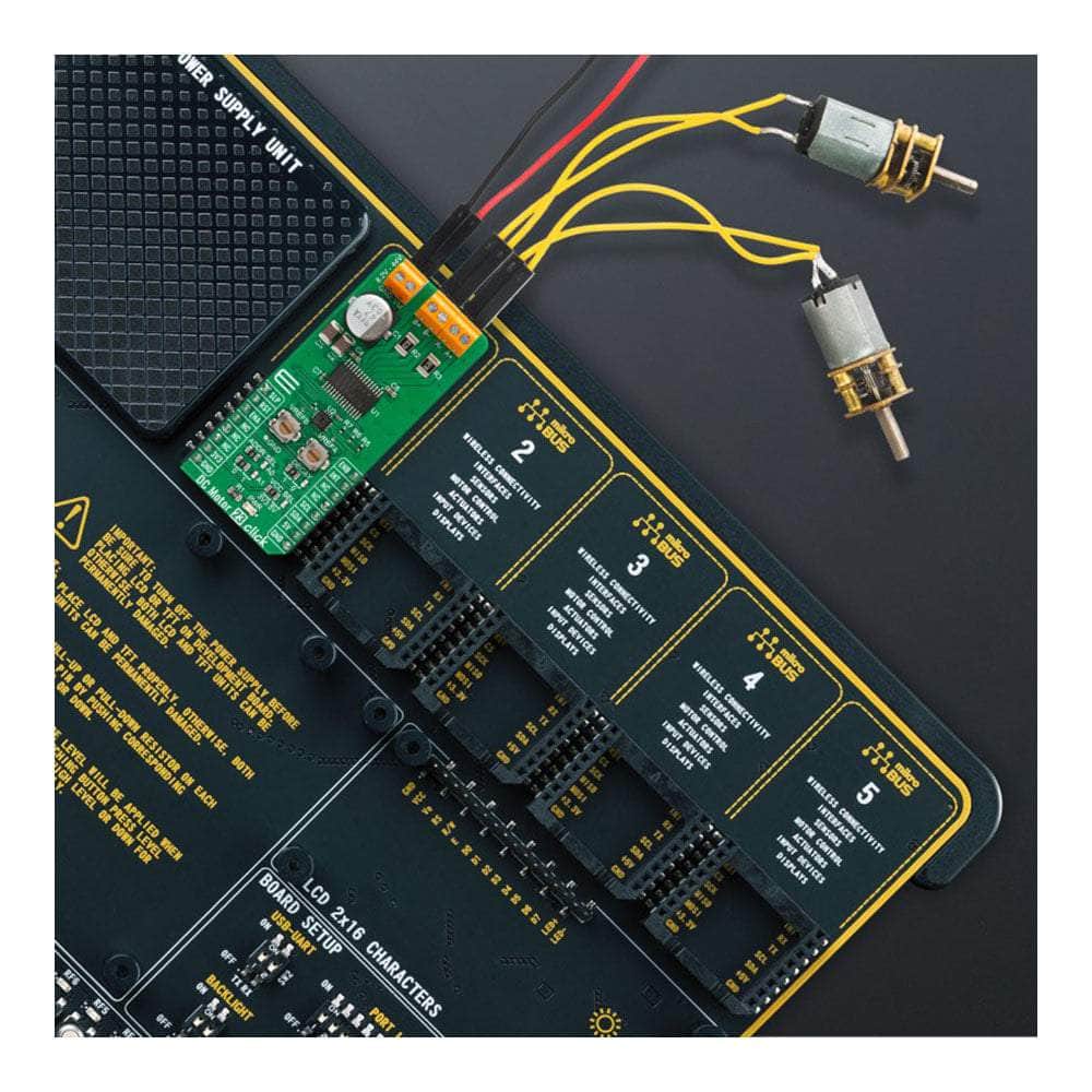
The DC Motor 23 Click Board™ supports an external power supply for the TB67H480FNG, which can be connected to the input terminal labelled as VM and should be within the range of 8.2V to 44V, while the two brushed or one stepping motor coils can be connected to the terminals labelled as B+, B-, A-, and A+.
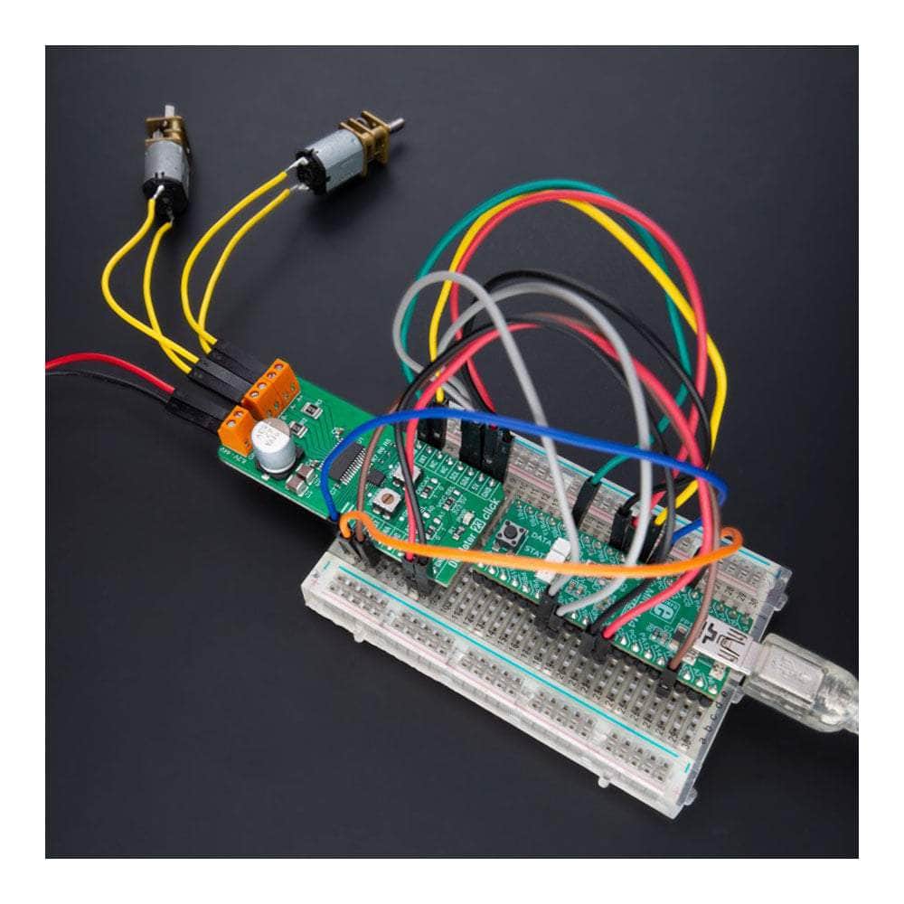
This Click board™ can operate with either 3.3V or 5V logic voltage levels selected via the VCC SEL jumper. This way, both 3.3V and 5V capable MCUs can use the communication lines properly. However, the Click board™ comes equipped with a library containing easy-to-use functions and an example code that can be used, as a reference, for further development.
SPECIFICATIONS
| Type | Brushed |
| Applications | It can be used for driving two-brushed or one-stepping motors in various applications such as consumer electronics and industrial equipment |
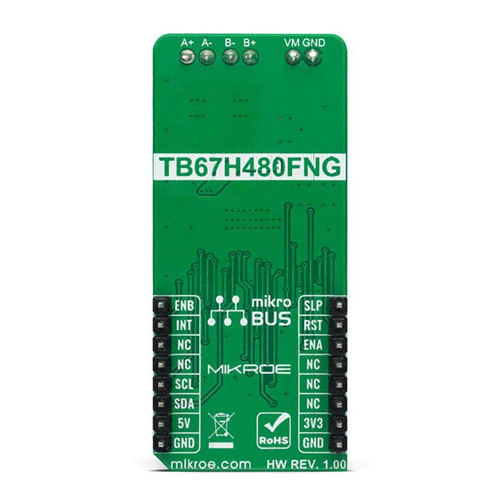
| On-board modules | TB67H480FNG - dual-channel, H-bridge, brushed DC motor driver from Toshiba Semiconductor |
| Key Features | Low power consumption, BiCD-based structure, high breakdown voltage/large current, power saving function, various protection features, selectable decay mode, error detection function, and more |
| Interface | GPIO, I2C |
| Compatibility | mikroBUS |
| Click board size | L (57.15 x 25.4 mm) |
| Input Voltage | 3.3V or 5V |
PINOUT DIAGRAM
This table shows how the pinout of the DC Motor 23 Click Board™ corresponds to the pinout on the mikroBUS™ socket (the latter shown in the two middle columns).
| Notes | Pin | Pin | Notes | ||||
|---|---|---|---|---|---|---|---|
| Sleep Mode | SLP | 1 | AN | PWM | 16 | ENB | Motor B Channel Control |
| Reset | RST | 2 | RST | INT | 15 | INT | Interrupt |
| Motor A Channel Control | ENA | 3 | CS | RX | 14 | NC | |
| NC | 4 | SCK | TX | 13 | NC | ||
| NC | 5 | MISO | SCL | 12 | SCL | I2C Clock | |
| NC | 6 | MOSI | SDA | 11 | SDA | I2C Data | |
| Power Supply | 3.3V | 7 | 3.3V | 5V | 10 | 5V | Power Supply |
| Ground | GND | 8 | GND | GND | 9 | GND | Ground |
ONBOARD SETTINGS AND INDICATORS
| Label | Name | Default | Description |
|---|---|---|---|
| LD1 | PWR | - | Power LED Indicator |
| JP1 | VCC SEL | Left | Logic Level Voltage Selection 3V3/5V: Left position 3V3, Right position 5V |
| JP2 | DECAY | Left | Decay Mode Selection 0/1: Left position 0, Right position 1 |
| JP3-JP4 | ADDR SEL | Left | I2C Address Selection 0/1: Left position 0, Right position 1 |
| VREFA | VREFA | - | Motor A Current Threshold Trimmer |
| VREFB | VREFB | - | Motor B Current Threshold Trimmer |
DC MOTOR 23 CLICK ELECTRICAL SPECIFICATIONS
| Description | Min | Typ | Max | Unit |
|---|---|---|---|---|
| Supply Voltage | 3.3 | - | 5 | V |
| External Supply Voltage VM | 8.2 | 24 | 44 | V |
| Maximum Output Voltage | - | - | 40 | V |
| Maximum Output Current | - | - | 2 | A |
Software Support
Software Support
We provide a library for the DC Motor 23 Click Board™ as well as a demo application (example), developed using MIKROE compilers. The demo can run on all the main MIKROE development boards.
The package can be downloaded/installed directly from NECTO Studio The package Manager (recommended), downloaded from our LibStock™ or found on MikroE Github account.
Library Description
This library contains API for the DC Motor 23 Click Board™ driver.
Key functions
-
dcmotor23_set_clockwiseDC Motor 23 set clockwise function. -
dcmotor23_set_counter_clockwiseDC Motor 23 set counterclockwise function. -
dcmotor23_set_decayDC Motor 23 set decay function.
Example Description
This example demonstrates the use of Dthe DC Motor 23 Click Board™. by driving the motors in both directions every 3 seconds.
void application_task ( void )
 {
     if ( DCMOTOR23_OK == dcmotor23_set_clockwise( &dcmotor23, DCMOTOR23_SEL_OUT_A ) )
     {
         log_printf ( &logger, " OUTA: Clockwisern" );
     }
     if ( DCMOTOR23_OK == dcmotor23_set_clockwise( &dcmotor23, DCMOTOR23_SEL_OUT_B ) )
     {
         log_printf ( &logger, " OUTB: Clockwisernn" );
     }
     Delay_ms ( 3000 );

     if ( DCMOTOR23_OK == dcmotor23_set_decay( &dcmotor23, DCMOTOR23_SEL_OUT_A ) )
     {
         log_printf ( &logger, " OUTA: Decayrn" );
     }
     if ( DCMOTOR23_OK == dcmotor23_set_decay( &dcmotor23, DCMOTOR23_SEL_OUT_B ) )
     {
         log_printf ( &logger, " OUTB: Decayrnn" );
     }
     Delay_ms ( 3000 );

     if ( DCMOTOR23_OK == dcmotor23_set_counter_clockwise( &dcmotor23, DCMOTOR23_SEL_OUT_A ) )
     {
         log_printf ( &logger, " OUTA: Counter-Clockwisern" );
     }
     if ( DCMOTOR23_OK == dcmotor23_set_counter_clockwise( &dcmotor23, DCMOTOR23_SEL_OUT_B ) )
     {
         log_printf ( &logger, " OUTB: Counter-Clockwisernn" );
     }
     Delay_ms ( 3000 );

     if ( DCMOTOR23_OK == dcmotor23_set_decay( &dcmotor23, DCMOTOR23_SEL_OUT_A ) )
     {
         log_printf ( &logger, " OUTA: Decayrn" );
     }
     if ( DCMOTOR23_OK == dcmotor23_set_decay( &dcmotor23, DCMOTOR23_SEL_OUT_B ) )
     {
         log_printf ( &logger, " OUTB: Decayrnn" );
     }
     log_printf ( &logger, "--------------------------rn" );
     Delay_ms ( 3000 );
 }
The full application code, and ready to use projects can be installed directly from NECTO Studio The package Manager (recommended), downloaded from our LibStock™ or found on MikroE Github account.
Other MikroE Libraries used in the example:
- MikroSDK.Board
- MikroSDK.Log
- Click.DCMotor23
Additional Notes and Information
Depending on the development board you are using, you may need USB UART Click Board™, USB UART 2 Click or RS232 Click to connect to your PC, for development systems with no UART to USB interface available on the board. UART terminal is available in all MIKROE compilers.
MIKROSDK
The DC Motor 23 Click Board™ is supported with mikroSDK - MIKROE Software Development Kit. To ensure proper operation of mikroSDK compliant Click board™ demo applications, mikroSDK should be downloaded from the LibStock and installed for the compiler you are using.
Carte à clic pour moteur à courant continu 23
Frequently Asked Questions
Have a Question?
Be the first to ask a question about this.