


Mikroelektronika d.o.o.
Carte à clic MUX 5
Carte à clic MUX 5
SKU: MIKROE-5423
Impossible de charger la disponibilité du service de retrait


Key Features
Overview
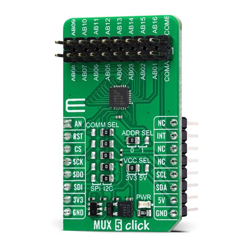
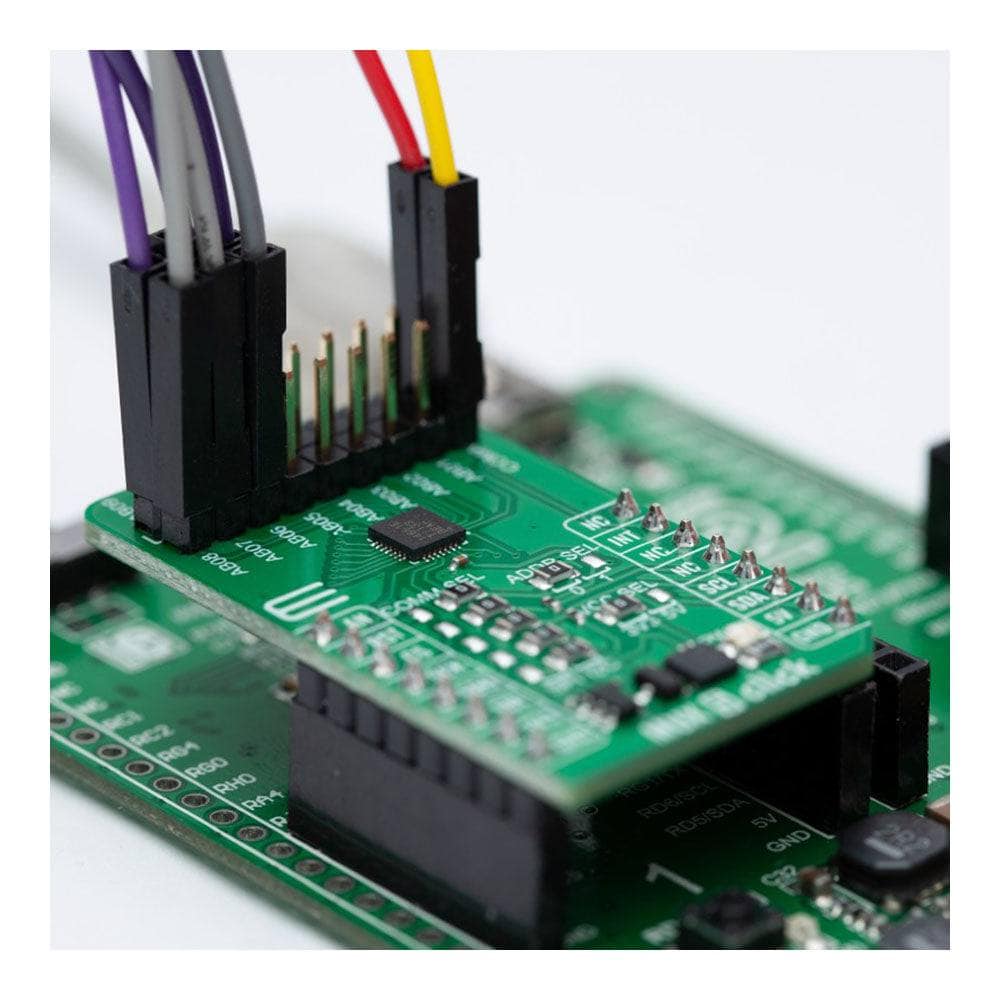
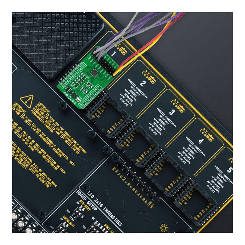
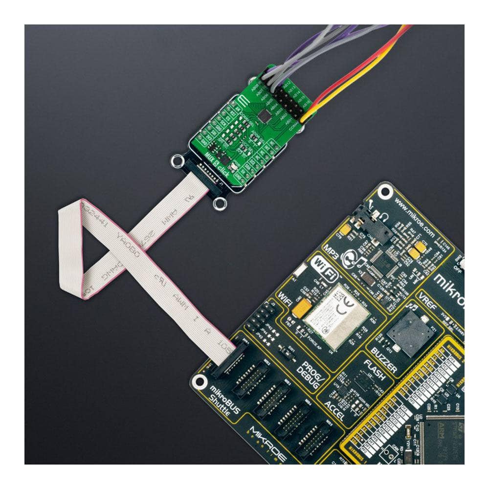
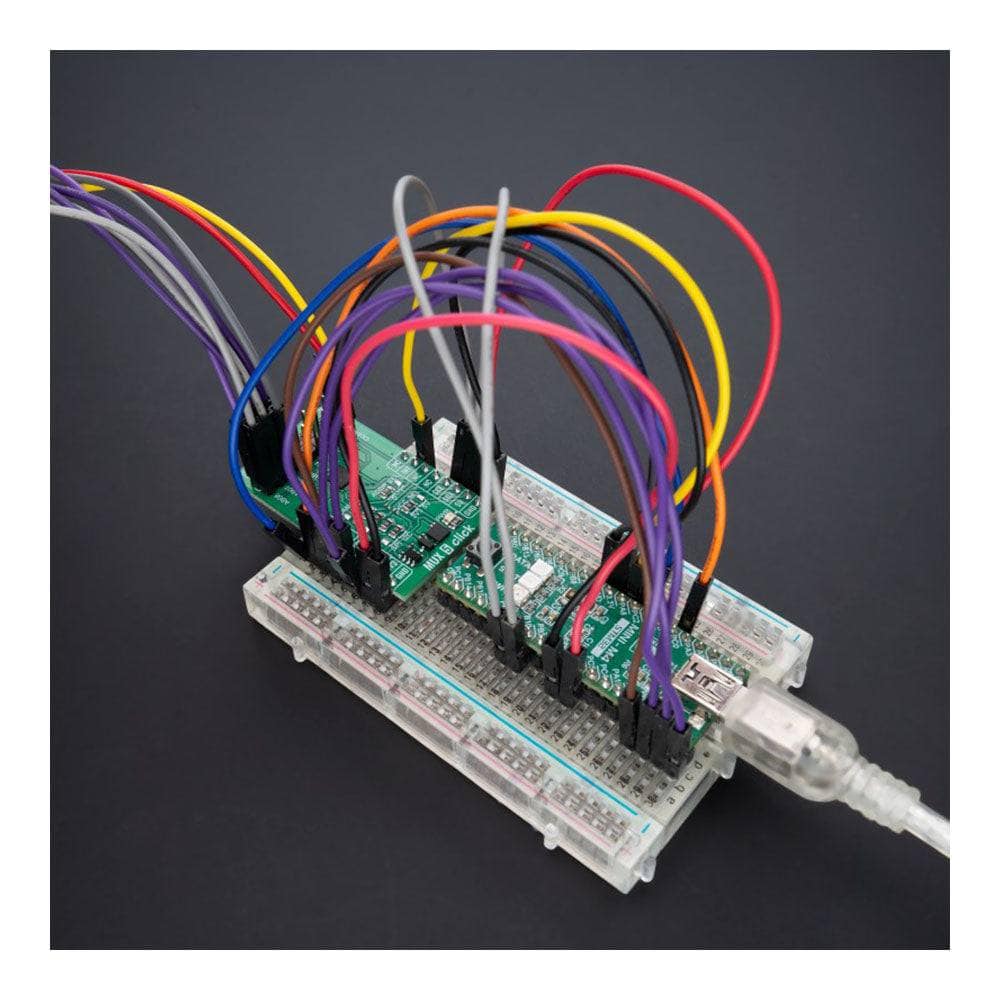
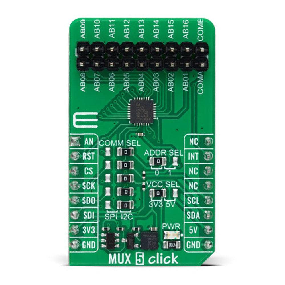
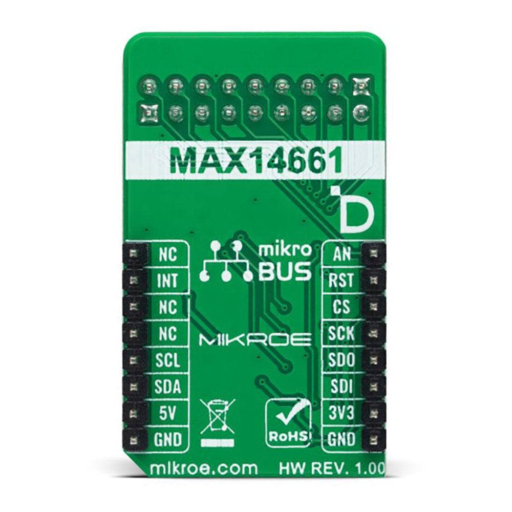
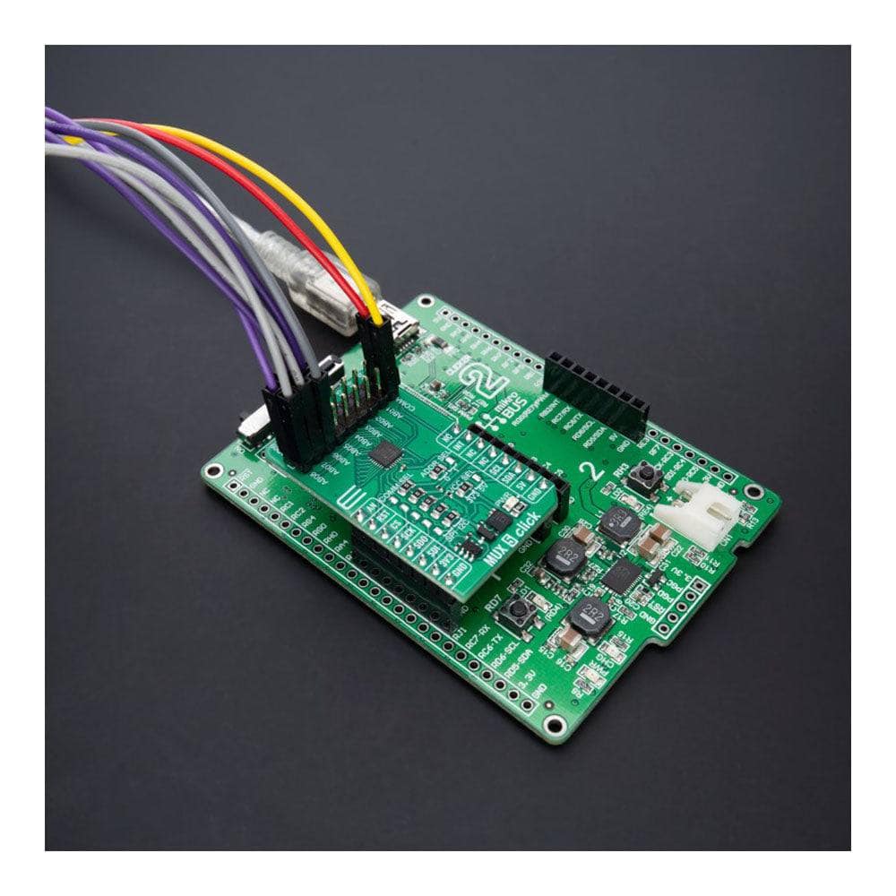
The MUX 5 Click Board™ is a compact add-on board that contains a precise multiplexing solution. This board features the MAX14661, a serially controlled, dual-channel analogue multiplexer from Analog Devices, allowing any of the 16 pins to be connected to either common pin simultaneously in any combination. The MAX14661 features Beyond-the-Rails™ capability that allows ±5.5V signals to be passed with any supply configuration alongside a configurable host interface that supports SPI and I2C serial communications. Both modes provide individual control of each independent switch so that any combination of switches can be applied. This Click board™ is designed to support various multiplexing applications like system diagnostics, data acquisition, signal switching, and many more.
The MUX 5 Click Board™ is supported by a mikroSDK-compliant library, which includes functions that simplify software development. This Click board™ comes as a thoroughly tested product, ready to be used on a system equipped with the mikroBUS™ socket.
Downloads
La carte Click Board™ MUX 5 est une carte complémentaire compacte qui contient une solution de multiplexage précise. Cette carte est équipée du MAX14661, un multiplexeur analogique à double canal contrôlé en série d'Analog Devices, permettant de connecter simultanément n'importe laquelle des 16 broches à l'une ou l'autre des broches communes dans n'importe quelle combinaison. Le MAX14661 est doté de la fonctionnalité Beyond-the-Rails™ qui permet de transmettre des signaux ±5,5 V avec n'importe quelle configuration d'alimentation ainsi qu'une interface hôte configurable qui prend en charge les communications série SPI et I2C. Les deux modes offrent un contrôle individuel de chaque commutateur indépendant afin que n'importe quelle combinaison de commutateurs puisse être appliquée. Cette carte Click™ est conçue pour prendre en charge diverses applications de multiplexage telles que les diagnostics système, l'acquisition de données, la commutation de signaux et bien d'autres encore.
La carte Click Board™ MUX 5 est supportée par une bibliothèque compatible mikroSDK, qui comprend des fonctions qui simplifient le développement logiciel. Cette carte Click Board™ est un produit entièrement testé, prêt à être utilisé sur un système équipé du socket mikroBUS™.
| General Information | |
|---|---|
Part Number (SKU) |
MIKROE-5423
|
Manufacturer |
|
| Physical and Mechanical | |
Weight |
0.02 kg
|
| Other | |
EAN |
8606027386343
|
Frequently Asked Questions
Have a Question?
Be the first to ask a question about this.