Étape 3 Cliquez sur le tableau
Overview
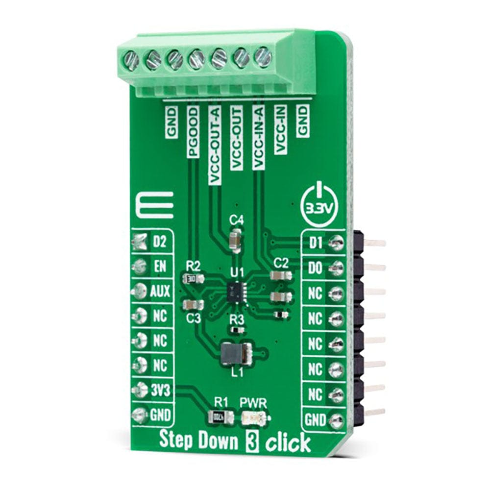
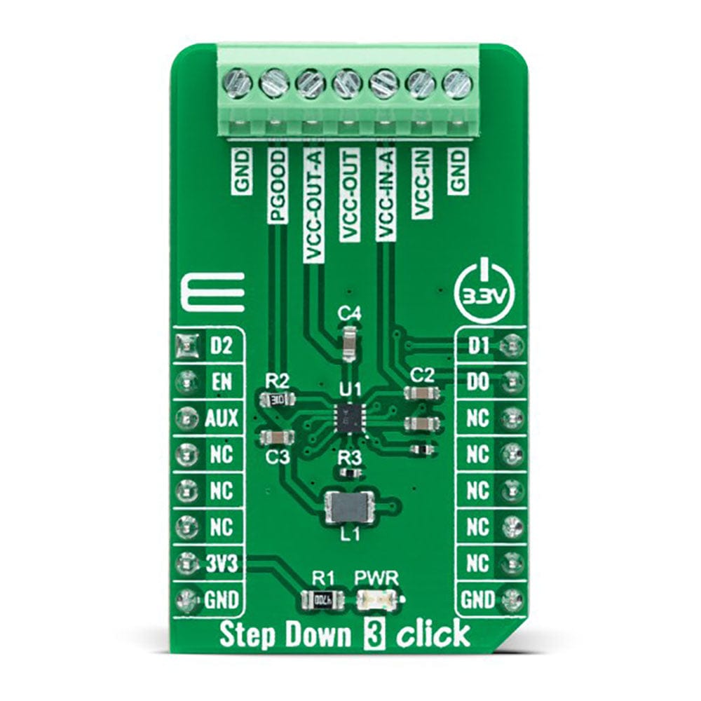
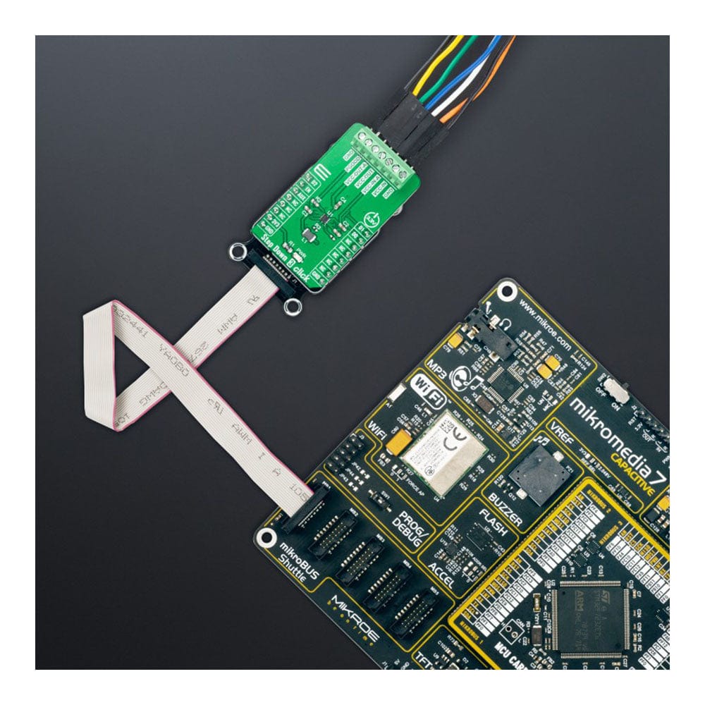
La carte Click Board™ Step Down 3 est une carte complémentaire compacte qui abaisse la tension de son entrée à sa sortie. Cette carte comprend le ST1PS03, un convertisseur abaisseur synchrone miniaturisé nano-quiescent avec un commutateur de charge de STMicroelectronics. Le ST1PS03 peut fournir jusqu'à 400 mA de courant de sortie avec une tension d'entrée comprise entre 1,8 V et 5,5 V, spécialement conçu pour les applications où un rendement élevé est crucial. Il intègre également un commutateur contrôlé accessible depuis l'entrée du canal auxiliaire pour alimenter un sous-système, une tension de sortie de 1,6 V à 3,3 V définie à l'aide de trois entrées de commande numériques et un signal Power Good pour indiquer les tensions de sortie stabilisées. Cette carte Click Board™ convient aux solutions de conversion de puissance dans les moniteurs de suivi personnel, la récupération d'énergie, les capteurs industriels, les appareils portables à faible consommation, etc.
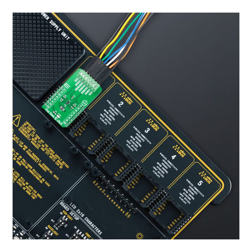
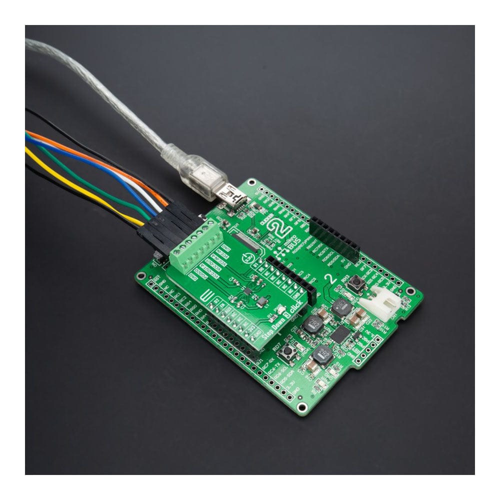
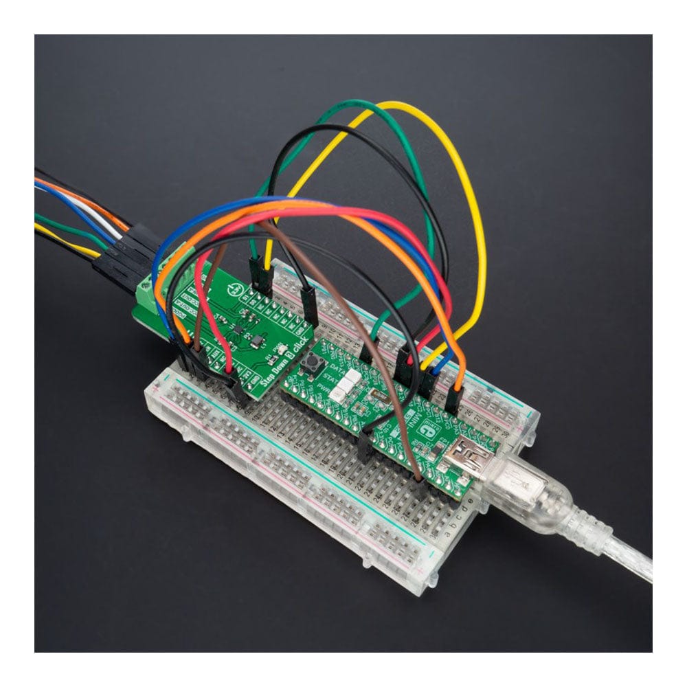
La carte Click Board™ Step Down 3 est prise en charge par une bibliothèque compatible mikroSDK, qui comprend des fonctions qui simplifient le développement logiciel. Cette carte Click Board™ est un produit entièrement testé, prêt à être utilisé sur un système équipé du socket mikroBUS™.
How Does The Step Down 3 Click Board™ Work?
The Step Down 3 Click Board™ is based on the ST1PS03, an ultra-low quiescent new generation buck converter from STMicroelectronics. The ST1PS03 targets a small quiescent current consumption, and it guarantees high-efficiency operation even down to a few microampere loads. It can provide up to 400mA output current with an output voltage from 1.6V to 3.3V on the VCC-OUT terminal, selectable using three digital control pins routed to the INT, PWM, and AN pins of the mikroBUS™ socket, and an input voltage ranging from 1.8V to 5.5V appliable on VCC-IN terminal.
The ST1PS03 is based on a hysteretic comparator that senses the coil ripple current, held constant in all operation modes. The ST1PS03 changes the switching frequency depending on the input supply voltage to maintain a continuous ripple current on the selected coil. It has a seamless transition between PFM (pulse frequency modulation) and PWM (pulse width modulation) mode with low ripple and good load transient response. During PWM mode (heavy load), the device operates in continuous conduction up to 400mA and a switching frequency of 2MHz maximum.
The device enters 100% duty cycle operation if the input voltage comes close to the selected output voltage. The regulator is turned OFF during this mode, and the output pin is directly connected to the input pin through the internal high-side MOSFET. Once the input voltage exceeds the 100% duty cycle, the device restarts to switch and regulates the output voltage again. This Click board™ also has a Power Good comparator which monitors the selected output voltage and provides information on the appropriate PGOOD terminal.
The Step Down 3 Click Board™ communicates with MCU using several GPIO pins. The AUX pin routed to the CS pin of the mikroBUS™ socket controls the auxiliary output terminal labelled as VCC-OUT-A. It provides the same regulated voltage level as VCC-IN-a input voltage, less drop on the load switch circuitry when the AUX pin and EN pin, routed to the RST pin of the mikroBUS™ socket, are tied high. The VCC-OUT-A terminal allows connecting/disconnecting the other system load to the output of the ST1PS03.
The Step Down 3 Click Board™ can be operated only with a 3.3V logic voltage level. The board must perform appropriate logic voltage level conversion before using MCUs with different logic levels. However, the Click board™ comes equipped with a library containing functions and an example code that can be used, as a reference, for further development.
SPECIFICATIONS
Type | Buck |
Applications | Can be used for power conversion solutions in personal tracking monitors, energy harvesting, industrial sensors, portable low power devices, and more |
On-board modules | ST1PS03 - ultra-low quiescent new generation buck converter from STMicroelectronics |
Key Features | Nano-quiescent synchronous step-down converter, output voltage selection, Power Good indicator, load switch controlled by auxiliary channel, undervoltage lockout, low power consumption, high efficiency, and more |
Interface | GPIO |
Compatibility | mikroBUS |
Click board size | M (42.9 x 25.4 mm) |
Input Voltage | 3.3V |
PINOUT DIAGRAM
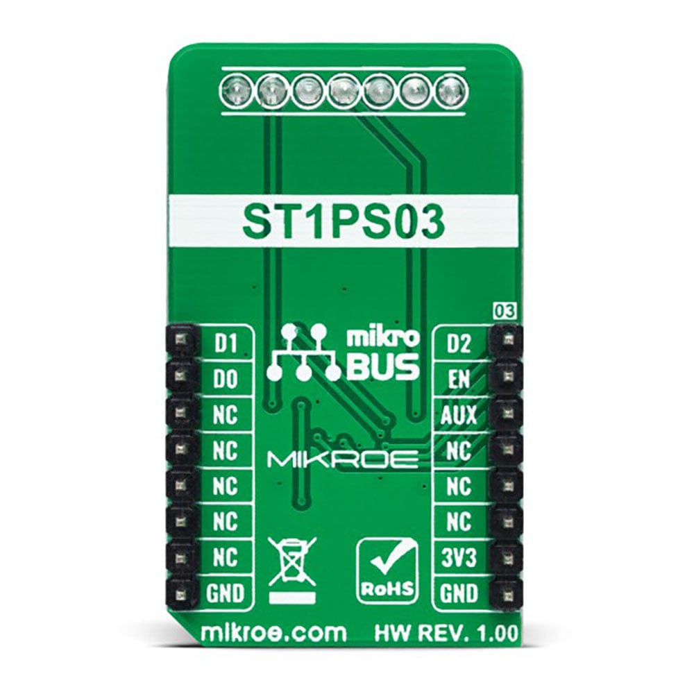
This table shows how the pinout of the Step Down 3 Click Board™ corresponds to the pinout on the mikroBUS™ socket (the latter shown in the two middle columns).
Notes | Pin | Pin | Notes | ||||
---|---|---|---|---|---|---|---|
Output Voltage Selection Pin 2 | D2 | 1 | AN | PWM | 16 | D1 | Output Voltage Selection Pin 1 |
Device Enable | EN | 2 | RST | INT | 15 | D0 | Output Voltage Selection Pin 0 |
Auxiliary | AUX | 3 | CS | RX | 14 | NC | |
NC | 4 | SCK | TX | 13 | NC | ||
NC | 5 | MISO | SCL | 12 | NC | ||
NC | 6 | MOSI | SDA | 11 | NC | ||
Power Supply | 3.3V | 7 | 3.3V | 5V | 10 | NC | |
Ground | GND | 8 | GND | GND | 9 | GND | Ground |
ONBOARD SETTINGS AND INDICATORS
Label | Name | Default | Description |
---|---|---|---|
LD1 | PWR | - | Power LED Indicator |
STEP DOWN 3 CLICK ELECTRICAL SPECIFICATIONS
Description | Min | Typ | Max | Unit |
---|---|---|---|---|
Supply Voltage VCC | - | 3.3 | - | V |
External Supply Voltage VCC-IN | 1.8 | - | 5.5 | V |
Output Voltage VCC-OUT | 1.6 | - | 3.3 | V |
Auxiliary Input Voltage VCC-IN-A | 0 | - | 5.5 | V |
Auxiliary Output Current VCC-OUT-A | - | - | 100 | mA |
Switching Frequency | - | - | 2 | MHz |
Operating Temperature Range | -40 | +25 | +120 | °C |
Software Support
We provide a library for the Step Down 3 Click Board™ as well as a demo application (example), developed using MikroElektronika compilers. The demo can run on all the main MikroElektronika development boards.
The package can be downloaded/installed directly from NECTO Studio The package Manager (recommended), downloaded from our LibStock™ or found on MikroE Github account.
Library Description
This library contains API for the Step Down 3 Click Board™ driver.
Key functions
-
stepdown3_enable_device
This function enables the auxiliary output (VOUT_AUX) by setting the AUX pin to HIGH logic state. -
stepdown3_enable_aux_output
This function disables the auxiliary output (VOUT_AUX) by setting the AUX pin to LOW logic state. -
stepdown3_set_output_voltage
This function sets the output voltage by setting the D2, D1, and D0 pins to a desired state.
Example Description
This example demonstrates the use of the Step Down 3 Click Board™ by iterating through the entire output voltage range.
void application_task ( void )
{
static uint8_t vout = STEPDOWN3_OUT_VOLTAGE_1V6;
stepdown3_set_output_voltage ( &stepdown3, vout );
switch ( vout )
{
case STEPDOWN3_OUT_VOLTAGE_1V6:
{
log_printf( &logger, " Output voltage: 1.6 Vrnn" );
break;
}
case STEPDOWN3_OUT_VOLTAGE_1V8:
{
log_printf( &logger, " Output voltage: 1.8 Vrnn" );
break;
}
case STEPDOWN3_OUT_VOLTAGE_2V1:
{
log_printf( &logger, " Output voltage: 2.1 Vrnn" );
break;
}
case STEPDOWN3_OUT_VOLTAGE_2V5:
{
log_printf( &logger, " Output voltage: 2.5 Vrnn" );
break;
}
case STEPDOWN3_OUT_VOLTAGE_2V7:
{
log_printf( &logger, " Output voltage: 2.7 Vrnn" );
break;
}
case STEPDOWN3_OUT_VOLTAGE_2V8:
{
log_printf( &logger, " Output voltage: 2.8 Vrnn" );
break;
}
case STEPDOWN3_OUT_VOLTAGE_3V0:
{
log_printf( &logger, " Output voltage: 3.0 Vrnn" );
break;
}
case STEPDOWN3_OUT_VOLTAGE_3V3:
{
log_printf( &logger, " Output voltage: 3.3 Vrnn" );
break;
}
}
if ( ++vout > STEPDOWN3_OUT_VOLTAGE_3V3 )
{
vout = STEPDOWN3_OUT_VOLTAGE_1V6;
}
Delay_ms ( 3000 );
}
The full application code, and ready to use projects can be installed directly from NECTO Studio The package Manager (recommended), downloaded from our LibStock™ or found on MikroE Github account.
Other MikroE Libraries used in the example:
- MikroSDK.Board
- MikroSDK.Log
- Click.StepDown3
Additional Notes and Information
Depending on the development board you are using, you may need USB UART Click Board™, USB UART 2 Click or RS232 Click to connect to your PC, for development systems with no UART to USB interface available on the board. UART terminal is available in all MikroElektronika compilers.
MIKROSDK
The Step Down 3 Click Board™ is supported with mikroSDK - MikroElektronika Software Development Kit. To ensure proper operation of mikroSDK compliant Click board™ demo applications, mikroSDK should be downloaded from the LibStock and installed for the compiler you are using.
Frequently Asked Questions
Have a Question?
Be the first to ask a question about this.