


Mikroelektronika d.o.o.
Carte Click I2C MUX 7
Carte Click I2C MUX 7
SKU: MIKROE-5069
Impossible de charger la disponibilité du service de retrait


Overview
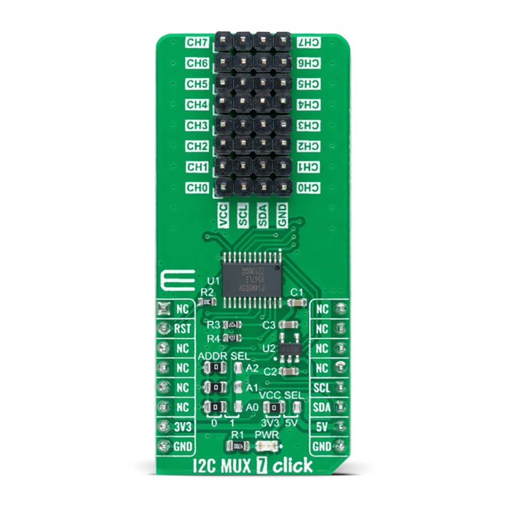
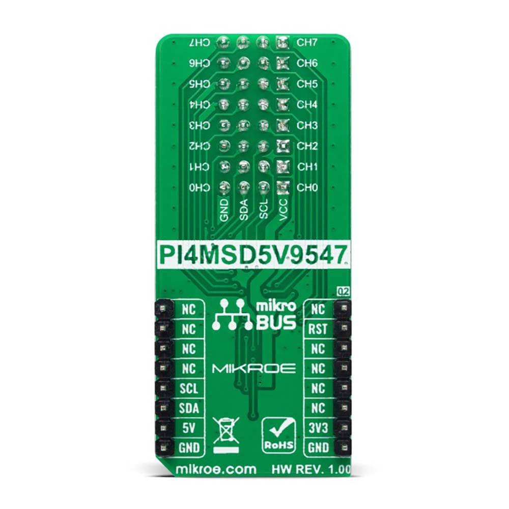
The I2C MUX 7 Click Board™ is a compact add-on board representing a bidirectional selector dedicated to applications with I2C slave address conflicts. This board features the PI4MSD5V9547, an octal bidirectional translating multiplexer controlled by the I2C-bus from Texas Instruments. Only one SCL/SDA channel can be selected at a time, determined by the contents of the programmable control register. The board powers up with Channel 0 connected, allowing immediate communication between the Master and downstream devices on that channel. The PI4MSD5V9547 also supports hot insertion, has a low Stand-by current, and has no glitch during the Power-Up sequence. This Click board™ is suitable for a wide range of applications from industrial to medical, communications, and automotive systems.
The I2C MUX 7 Click Board™ is supported by a mikroSDK compliant library, which includes functions that simplify software development. This Click board™ comes as a fully tested product, ready to be used on a system equipped with the mikroBUS™ socket.
Downloads
La carte Click Board™ I2C MUX 7 est une carte complémentaire compacte représentant un sélecteur bidirectionnel dédié aux applications avec conflits d'adresses esclaves I2C. Cette carte comprend le PI4MSD5V9547, un multiplexeur de traduction bidirectionnel octal contrôlé par le bus I2C de Texas Instruments. Un seul canal SCL/SDA peut être sélectionné à la fois, déterminé par le contenu du registre de contrôle programmable. La carte s'allume avec le canal 0 connecté, permettant une communication immédiate entre le maître et les périphériques en aval sur ce canal. Le PI4MSD5V9547 prend également en charge l'insertion à chaud, a un faible courant de veille et ne présente aucun problème pendant la séquence de mise sous tension. Cette carte Click™ convient à une large gamme d'applications, des systèmes industriels aux systèmes médicaux, de communication et automobiles.
La carte Click Board™ I2C MUX 7 est prise en charge par une bibliothèque compatible mikroSDK, qui comprend des fonctions qui simplifient le développement logiciel. Cette carte Click™ est livrée sous la forme d'un produit entièrement testé, prêt à être utilisé sur un système équipé du socket mikroBUS™.
| General Information | |
|---|---|
Part Number (SKU) |
MIKROE-5069
|
Manufacturer |
|
| Physical and Mechanical | |
Weight |
0.02 kg
|
| Other | |
EAN |
8606027389429
|
Frequently Asked Questions
Have a Question?
Be the first to ask a question about this.