


Mikroelektronika d.o.o.
Carte à clic Multi Stepper TB62262
Carte à clic Multi Stepper TB62262
SKU: MIKROE-5037
Impossible de charger la disponibilité du service de retrait
Overview
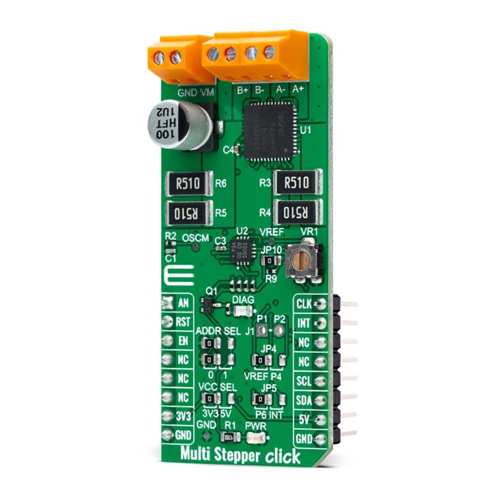
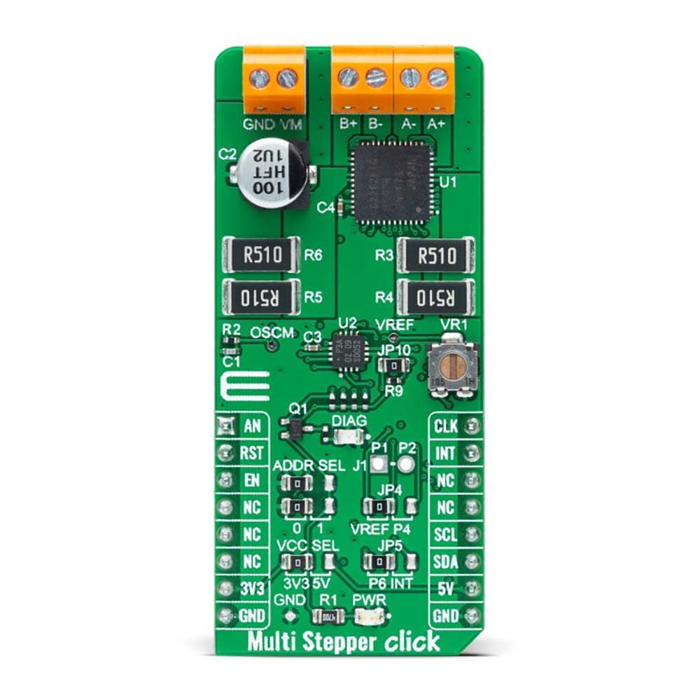
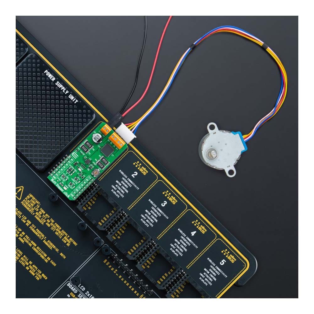
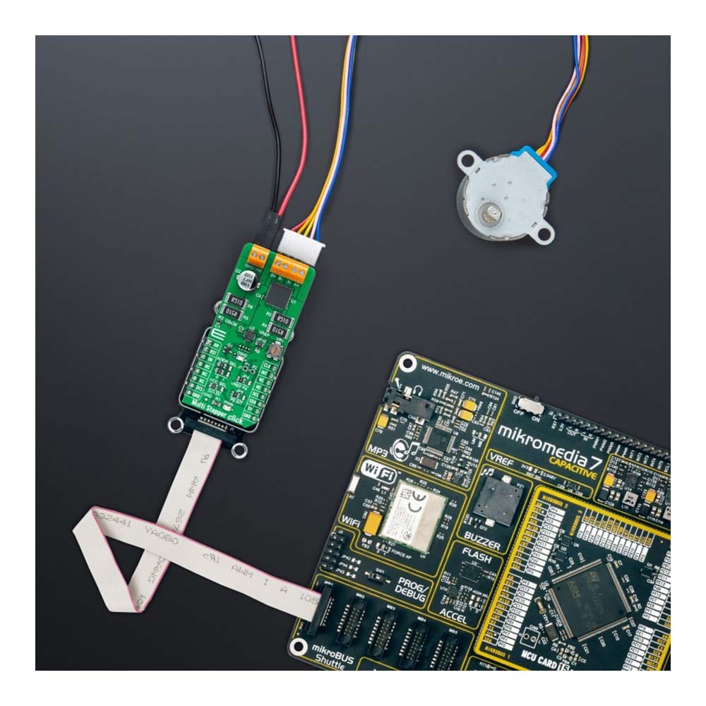
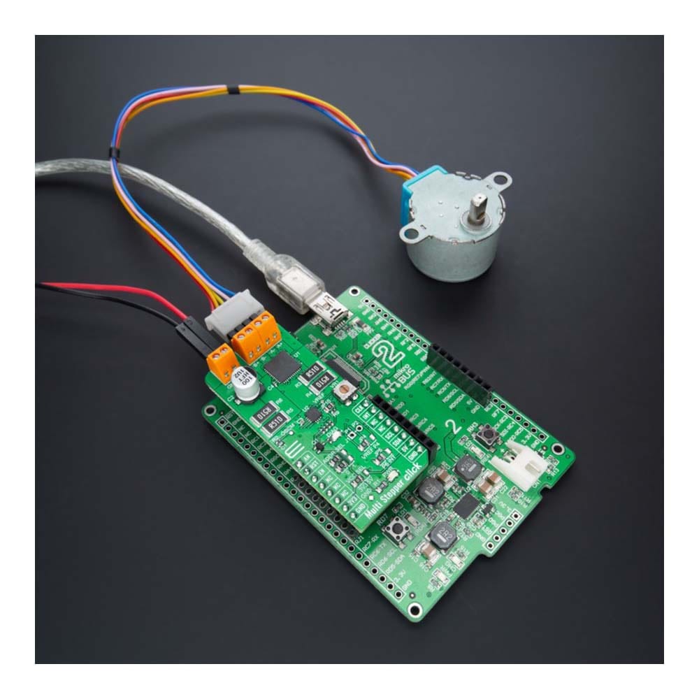
The Multi Stepper TB62262 Click Board™ is a compact add-on board that contains a bipolar stepper motor driver. This board features the TB62262FTG, CLOCK-in controlled bipolar stepping motor driver from Toshiba Semiconductor. It supports a PWM constant-current control drive and allows full-, half-, and quarter-step operation for less motor noise and smoother control. It has a wide operating voltage range of 10V to 38V with an output current capacity of 1.2A and several built-in error detection circuits. This Click board™ makes the perfect solution for stepping motors in various applications such as office automation, commercial and industrial equipment.
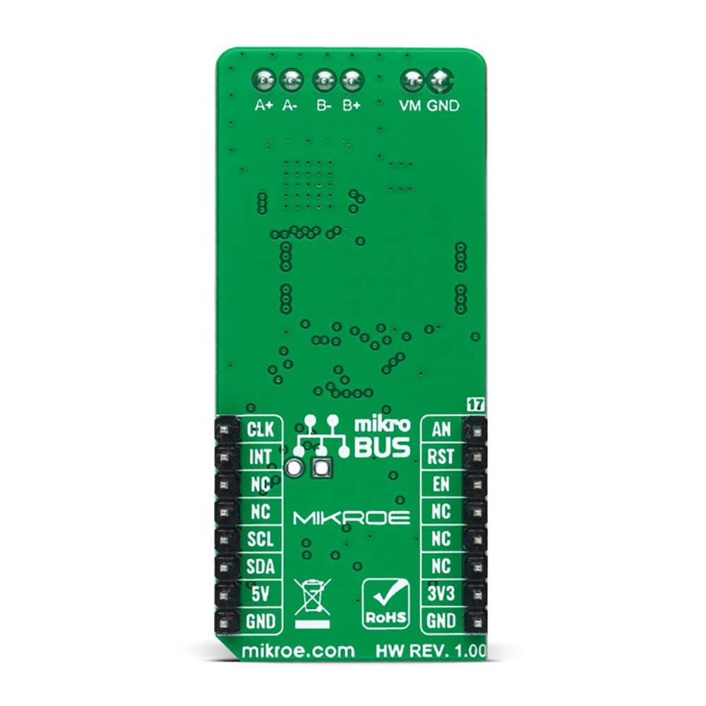
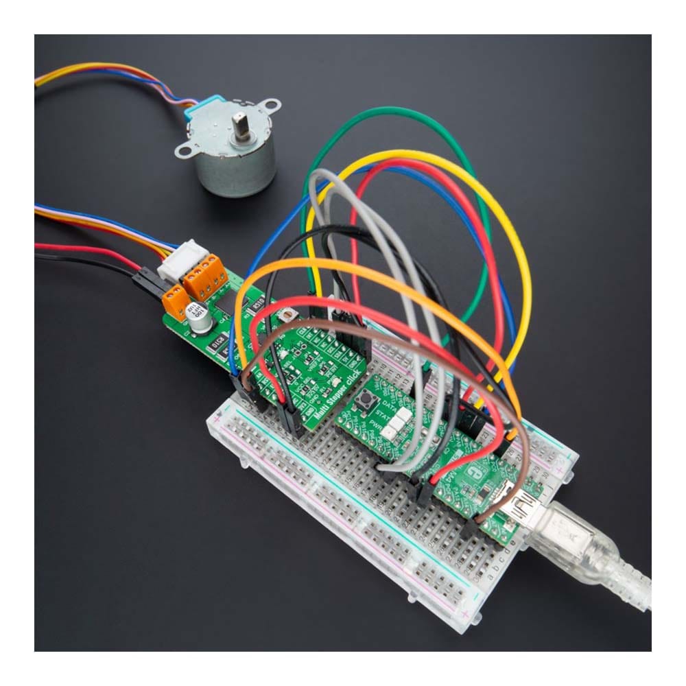
The Multi Stepper TB62262 Click Board™ is supported by a mikroSDK compliant library, which includes functions that simplify software development. This Click board™ comes as a thoroughly tested product, ready to be used on a system equipped with the mikroBUS™ socket.
Downloads
La carte Click Board™ Multi Stepper TB62262 est une carte complémentaire compacte qui contient un pilote de moteur pas à pas bipolaire. Cette carte est équipée du pilote de moteur pas à pas bipolaire TB62262FTG, contrôlé par CLOCK-in de Toshiba Semiconductor. Il prend en charge un variateur de courant constant PWM et permet un fonctionnement en pas complet, demi-pas et quart de pas pour moins de bruit moteur et un contrôle plus fluide. Il dispose d'une large plage de tension de fonctionnement de 10 V à 38 V avec une capacité de courant de sortie de 1,2 A et plusieurs circuits de détection d'erreur intégrés. Cette carte Click™ constitue la solution parfaite pour les moteurs pas à pas dans diverses applications telles que la bureautique, les équipements commerciaux et industriels.
La carte Click Board™ Multi Stepper TB62262 est prise en charge par une bibliothèque compatible mikroSDK, qui comprend des fonctions qui simplifient le développement logiciel. Cette carte Click Board™ est un produit entièrement testé, prêt à être utilisé sur un système équipé du socket mikroBUS™.
| General Information | |
|---|---|
Part Number (SKU) |
MIKROE-5037
|
Manufacturer |
|
| Physical and Mechanical | |
Weight |
0.02 kg
|
| Other | |
EAN |
8606027389153
|
Frequently Asked Questions
Have a Question?
Be the first to ask a question about this.