


Mikroelektronika d.o.o.
Carte à clic sans balais 17
Carte à clic sans balais 17
SKU: MIKROE-5000
Impossible de charger la disponibilité du service de retrait


Key Features
Overview
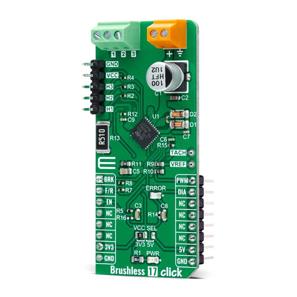
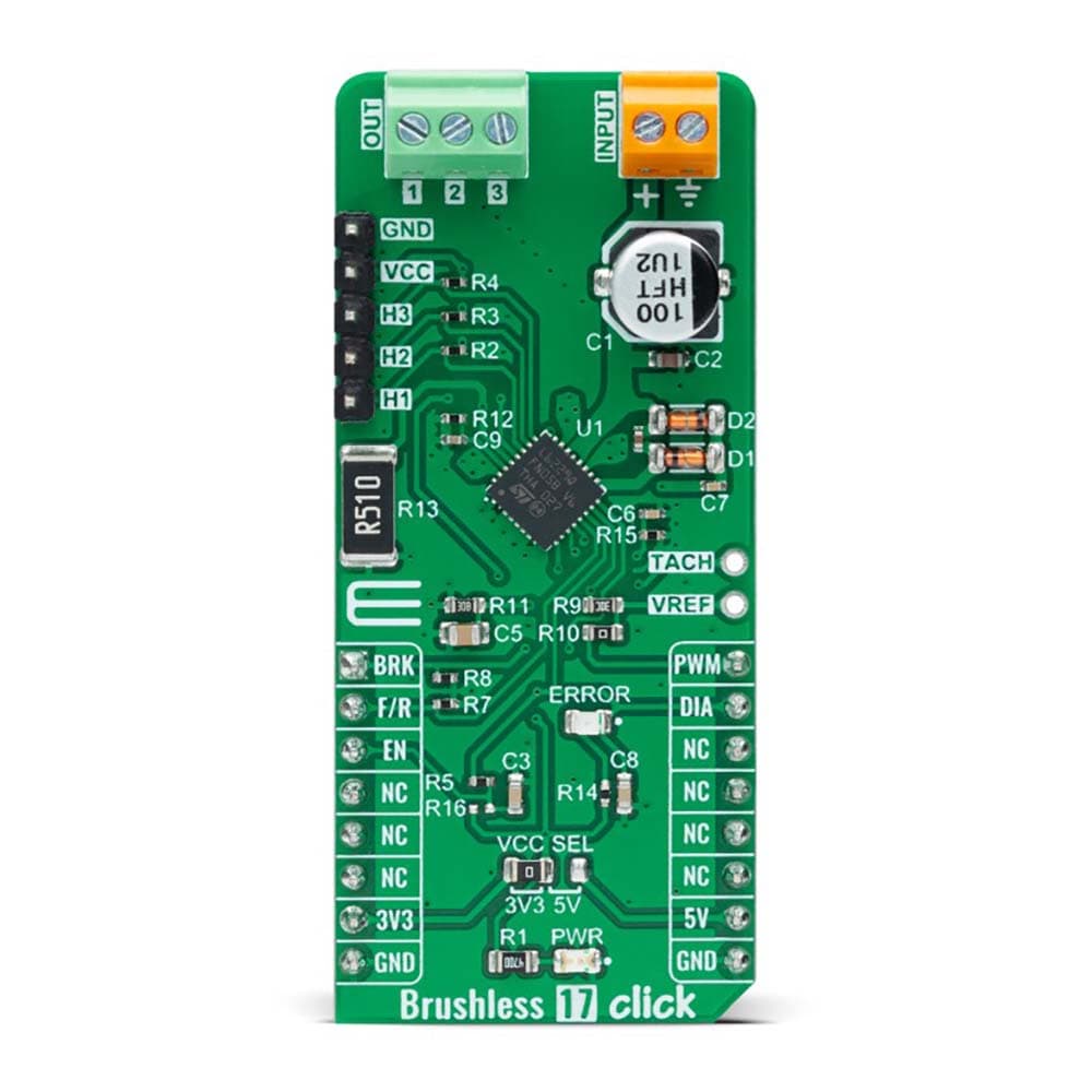
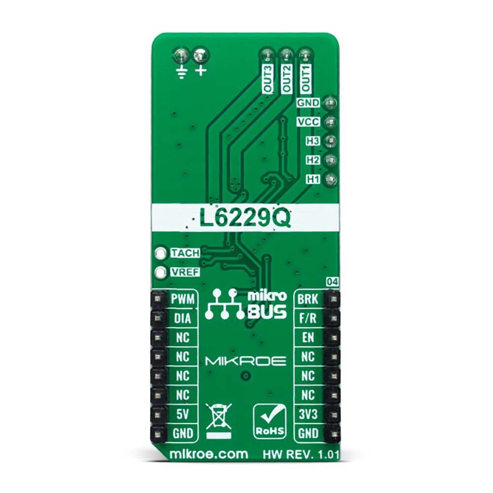
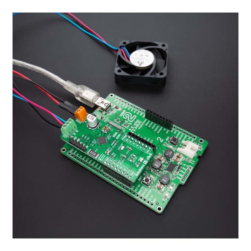
The Brushless 17 Click Board™ is a compact add-on board suitable for controlling brushless DC (BLDC) motors with any MCU. This board features the L6229Q, DMOS fully integrated three-phase BLDC motor driver with overcurrent protection from STMicroelectronics. This motor driver combines isolated DMOS power transistors with CMOS and bipolar circuits on the same chip, realized in BCD (Bipolar-CMOS-DMOS) multipower technology. It includes all the circuitry for a three-phase BLDC motor drive, including a three-phase DMOS bridge, a constant off-time PWM current controller, and the decoding logic for single-ended hall sensors that generate the required sequence for the power stage. This Click board™ makes the perfect solution for driving three-phase brushless DC motors with currents up to 1A DC.
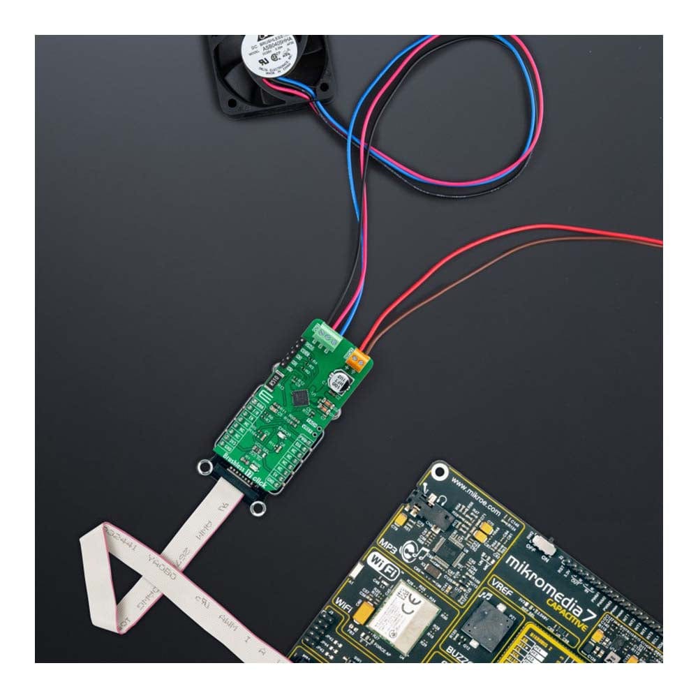
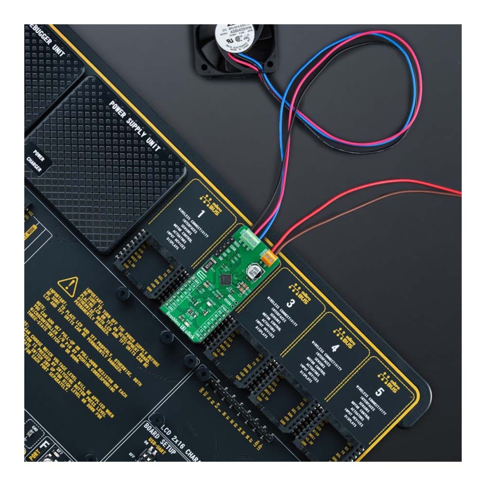
The Brushless 17 Click Board™ is supported by a mikroSDK compliant library, which includes functions that simplify software development. This Click board™ comes as a fully tested product, ready to be used on a system equipped with the mikroBUS™ socket.
Downloads
La carte Click Board™ Brushless 17 est une carte complémentaire compacte adaptée au contrôle des moteurs à courant continu sans balais (BLDC) avec n'importe quel microcontrôleur. Cette carte est équipée du pilote de moteur BLDC triphasé entièrement intégré DMOS L6229Q avec protection contre les surintensités de STMicroelectronics. Ce pilote de moteur combine des transistors de puissance DMOS isolés avec des circuits CMOS et bipolaires sur la même puce, réalisés en technologie multi-puissance BCD (Bipolar-CMOS-DMOS). Il comprend tous les circuits pour un entraînement de moteur BLDC triphasé, y compris un pont DMOS triphasé, un contrôleur de courant PWM à temps d'arrêt constant et la logique de décodage pour les capteurs à effet Hall à extrémité unique qui génèrent la séquence requise pour l'étage de puissance. Cette carte Click™ constitue la solution parfaite pour piloter des moteurs à courant continu sans balais triphasés avec des courants allant jusqu'à 1 A CC.
La carte Click Board™ Brushless 17 est supportée par une bibliothèque compatible mikroSDK, qui comprend des fonctions qui simplifient le développement logiciel. Cette carte Click Board™ est livrée sous la forme d'un produit entièrement testé, prêt à être utilisé sur un système équipé du socket mikroBUS™.
| General Information | |
|---|---|
Part Number (SKU) |
MIKROE-5000
|
Manufacturer |
|
| Physical and Mechanical | |
Weight |
0.02 kg
|
| Other | |
EAN |
8606027388620
|
Frequently Asked Questions
Have a Question?
Be the first to ask a question about this.