


Mikroelektronika d.o.o.
Carte à clic ADC 19
Carte à clic ADC 19
SKU: MIKROE-4997
Impossible de charger la disponibilité du service de retrait


Key Features
Overview
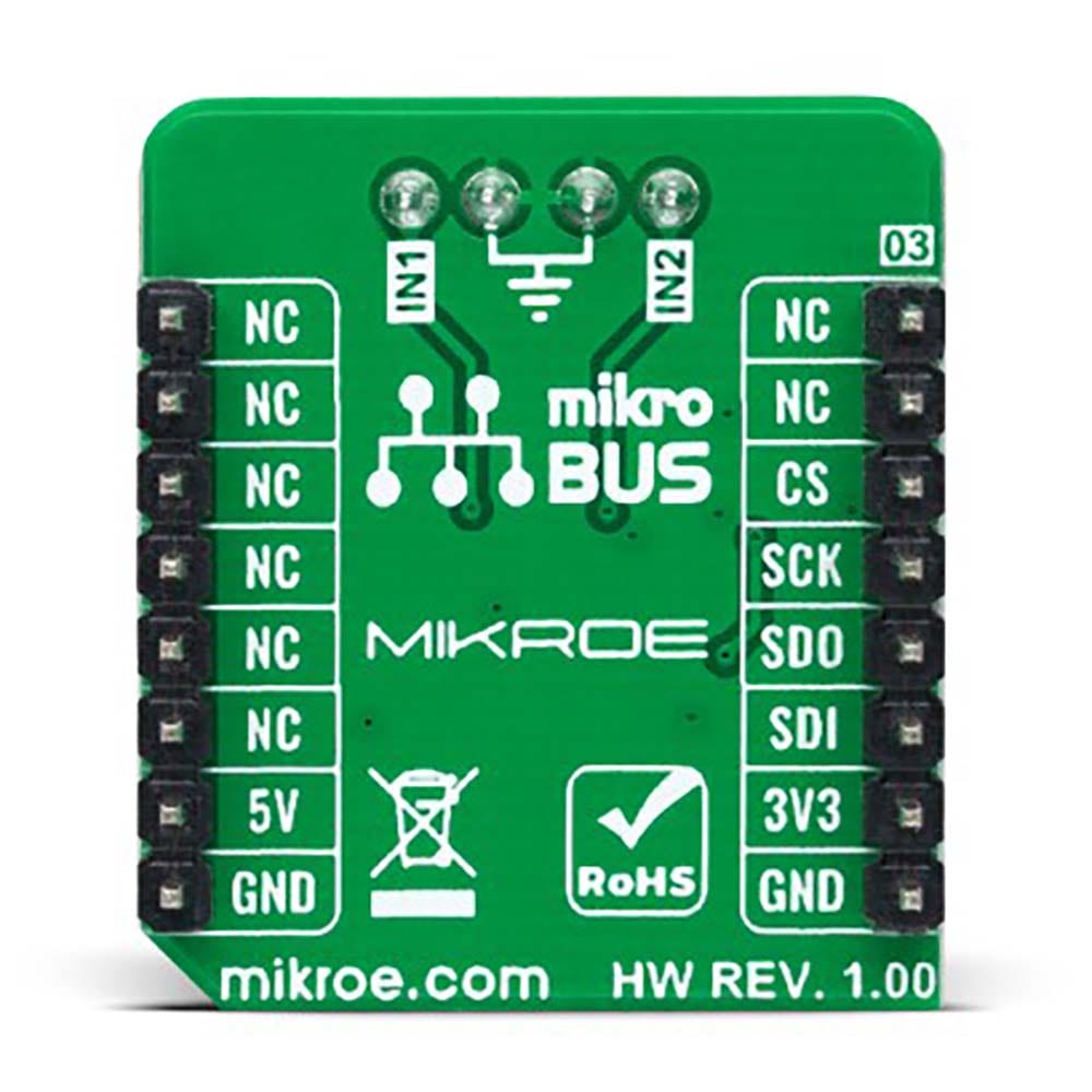
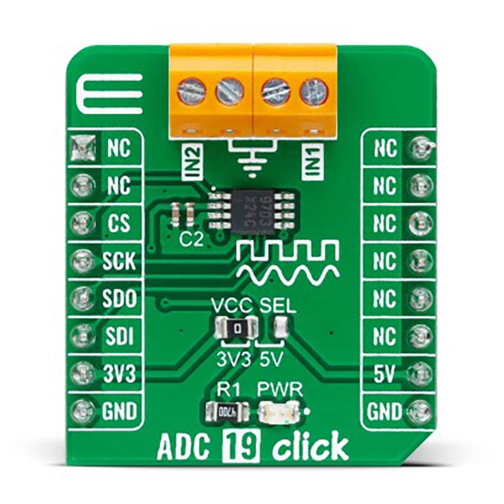
The ADC 19 Click Board™ is a compact add-on board that contains a high-performance data converter. This board features the ADC122S101, a low-power two-channel CMOS 12-bit analog-to-digital converter from Texas Instruments. This SPI configurable analog-to-digital converter (ADC) is fully specified over a sample rate range of 500ksps to 1Msps, offering high reliability and performance. The converter is based on a successive-approximation register architecture with an internal track-and-hold circuit configurable to accept one or two input signals at its input channels. This Click board™ offers high accuracy solution for the most demanding applications, from general-purpose remote data acquisition applications to portable consumer electronics and more.
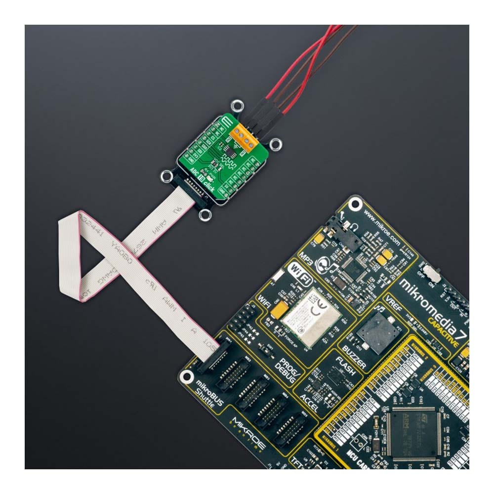
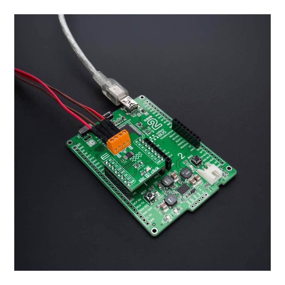
The ADC 19 Click Board™ is supported by a mikroSDK compliant library, which includes functions that simplify software development. This Click board™ comes as a fully tested product, ready to be used on a system equipped with the mikroBUS™ socket.
Downloads
La carte Click Board™ ADC 19 est une carte complémentaire compacte qui contient un convertisseur de données hautes performances. Cette carte comprend l'ADC122S101, un convertisseur analogique-numérique CMOS 12 bits à deux canaux à faible consommation de Texas Instruments. Ce convertisseur analogique-numérique (CAN) configurable SPI est entièrement spécifié sur une plage de fréquence d'échantillonnage de 500 ksps à 1 Msps, offrant une fiabilité et des performances élevées. Le convertisseur est basé sur une architecture de registre à approximations successives avec un circuit de suivi et de maintien interne configurable pour accepter un ou deux signaux d'entrée sur ses canaux d'entrée. Cette carte Click™ offre une solution de haute précision pour les applications les plus exigeantes, des applications d'acquisition de données à distance à usage général aux appareils électroniques grand public portables et plus encore.
La carte Click Board™ ADC 19 est prise en charge par une bibliothèque compatible mikroSDK, qui comprend des fonctions qui simplifient le développement logiciel. Cette carte Click Board™ est un produit entièrement testé, prêt à être utilisé sur un système équipé du socket mikroBUS™.
| General Information | |
|---|---|
Part Number (SKU) |
MIKROE-4997
|
Manufacturer |
|
| Physical and Mechanical | |
Weight |
0.02 kg
|
| Other | |
EAN |
8606027389054
|
Frequently Asked Questions
Have a Question?
Be the first to ask a question about this.