


Mikroelektronika d.o.o.
Horloge Gen 6 Click Board
Horloge Gen 6 Click Board
SKU: MIKROE-4973
Impossible de charger la disponibilité du service de retrait
Key Features
Overview
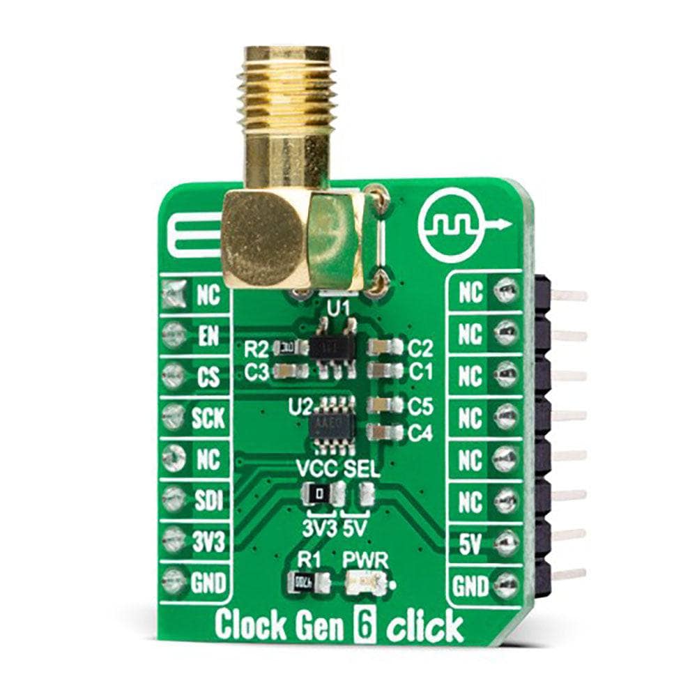
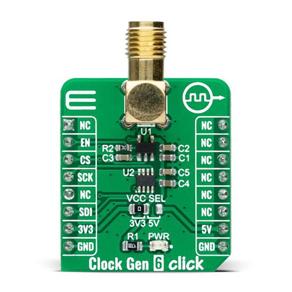
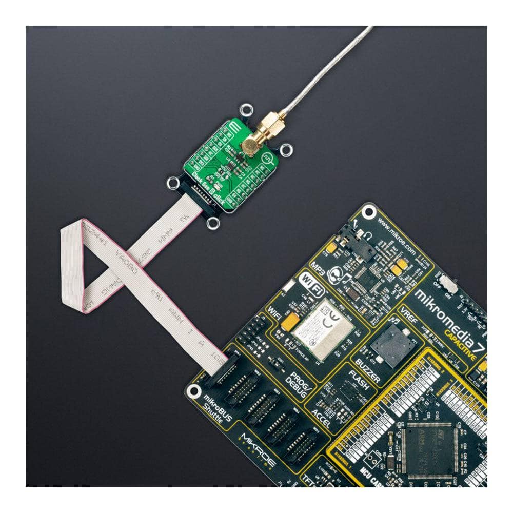
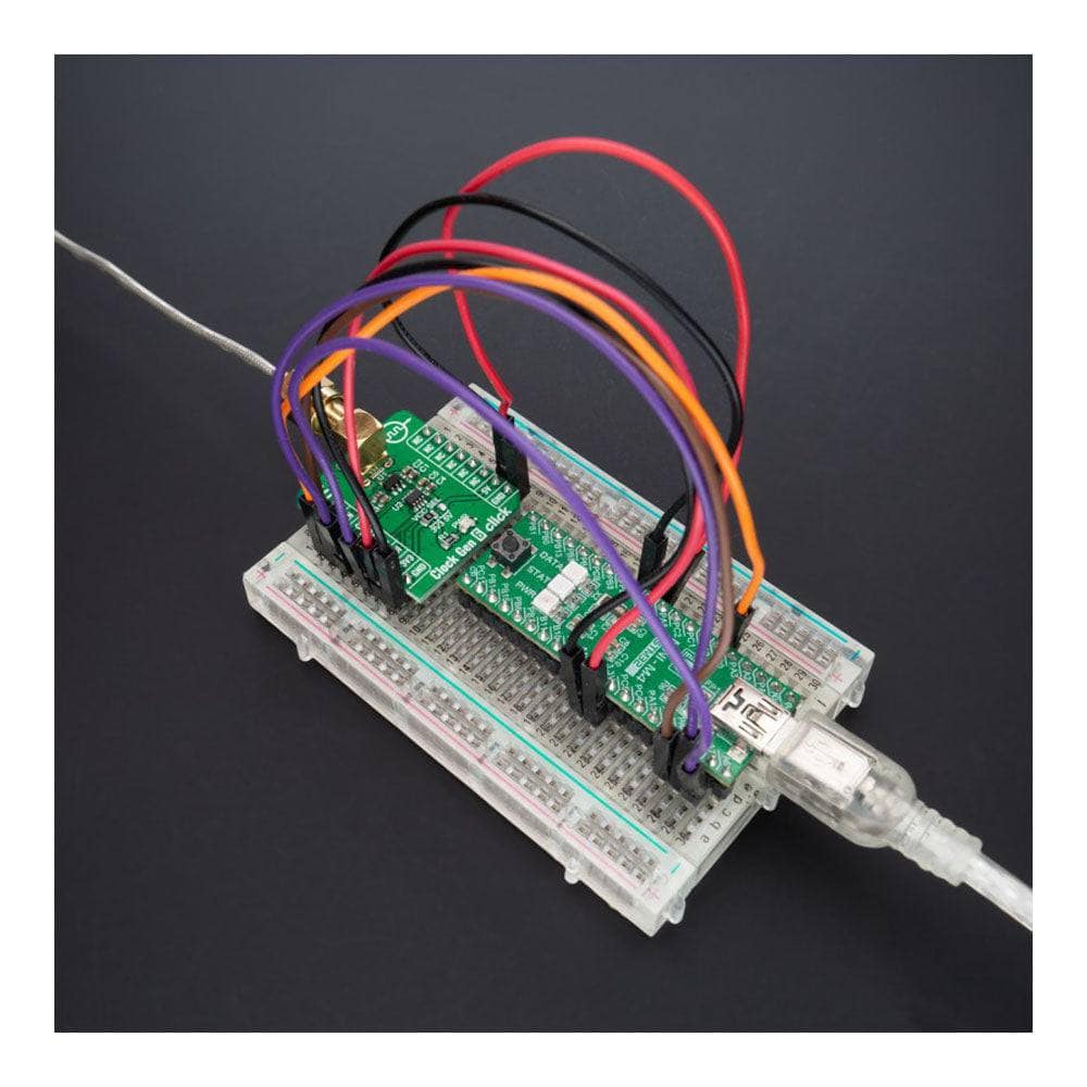
The Clock Gen 6 Click Board™ is a compact add-on board representing a digital oscillator solution. This board features the MIC1557, an IttyBitty CMOS RC oscillator designed to provide rail-to-rail pulses for precise time delay or frequency generation from Microchip Technology. The MIC1557 has a single threshold and trigger connection, internally connected, for astable (oscillator) operation only. It also has an enable/reset control signal routed to the RST pin of the mikroBUS™ socket, which controls the bias supply to the oscillator’s internal circuitry and optimizes power consumption used for oscillator power ON/OFF purposes. In addition, it provides the ability to select the desired frequency programmed via a digital potentiometer, the MAX5401. This Click board™ is suitable for pulse generation, precision timer, time-delay generation, and similar applications.
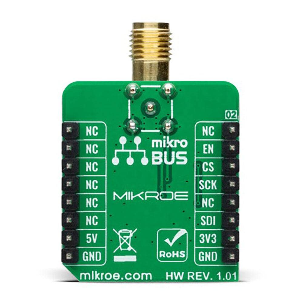
The Clock Gen 6 Click Board™ is supported by a mikroSDK compliant library, which includes functions that simplify software development. This Click board™ comes as a fully tested product, ready to be used on a system equipped with the mikroBUS™ socket.
Downloads
La carte Click Board™ Clock Gen 6 est une carte complémentaire compacte représentant une solution d'oscillateur numérique. Cette carte comprend le MIC1557, un oscillateur CMOS RC IttyBitty conçu pour fournir des impulsions rail-to-rail pour une temporisation précise ou une génération de fréquence de Microchip Technology. Le MIC1557 possède une connexion de seuil et de déclenchement unique, connectée en interne, pour un fonctionnement astable (oscillateur) uniquement. Il dispose également d'un signal de commande d'activation/réinitialisation acheminé vers la broche RST de la prise mikroBUS™, qui contrôle l'alimentation de polarisation vers les circuits internes de l'oscillateur et optimise la consommation d'énergie utilisée pour la mise sous/hors tension de l'oscillateur. De plus, il offre la possibilité de sélectionner la fréquence souhaitée programmée via un potentiomètre numérique, le MAX5401. Cette carte Click™ convient à la génération d'impulsions, à la minuterie de précision, à la génération de temporisation et à des applications similaires.
La carte Click™ Clock Gen 6 est prise en charge par une bibliothèque compatible mikroSDK, qui comprend des fonctions qui simplifient le développement logiciel. Cette carte Click™ est livrée sous la forme d'un produit entièrement testé, prêt à être utilisé sur un système équipé du socket mikroBUS™.
| General Information | |
|---|---|
Part Number (SKU) |
MIKROE-4973
|
Manufacturer |
|
| Physical and Mechanical | |
Weight |
0.02 kg
|
| Other | |
EAN |
8606027388132
|
Frequently Asked Questions
Have a Question?
Be the first to ask a question about this.