


Mikroelektronika d.o.o.
Carte de clic RF Meter 3
Carte de clic RF Meter 3
SKU: MIKROE-4906
Impossible de charger la disponibilité du service de retrait


Overview
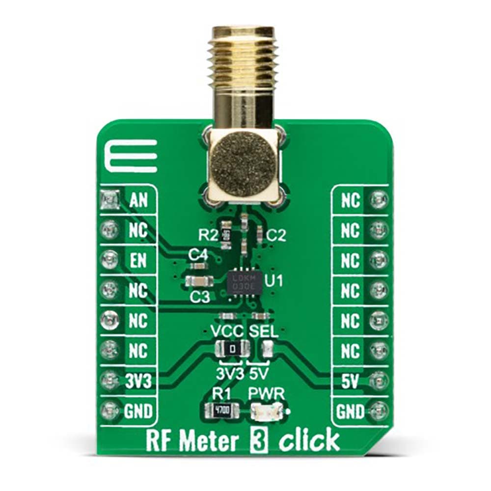
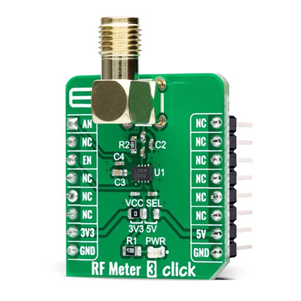
The RF Meter 3 Click Board™ is a compact add-on board that collects information, analyzes RF power, and displays information in an easy-to-read digital format. This board features the LT5581, a low-power monolithic precision RMS power detector from Analog Devices. The RMS detector uses a proprietary technique to accurately measure the RF power in a range from 2GHz up to 2.6GHz, well-suited for signals with high crest factors. It outputs a DC voltage in linear scale proportional to an RF input signal power in dBm. This Click board™ is suitable for precision power measurement and control for various RF standards, including GSM/EDGE, CDMA, CDMA2000, W-CDMA, TD-SCDMA, UMTS, LTE, and WiMAX.
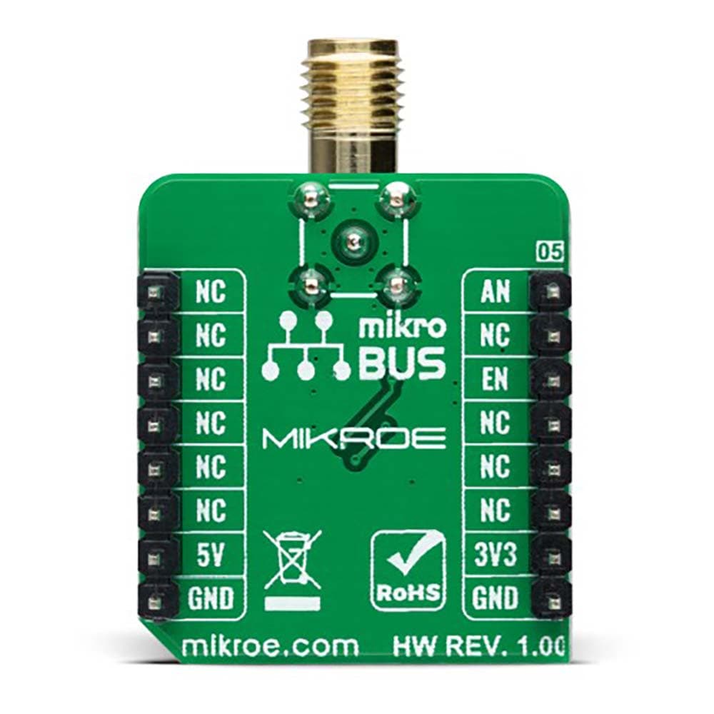
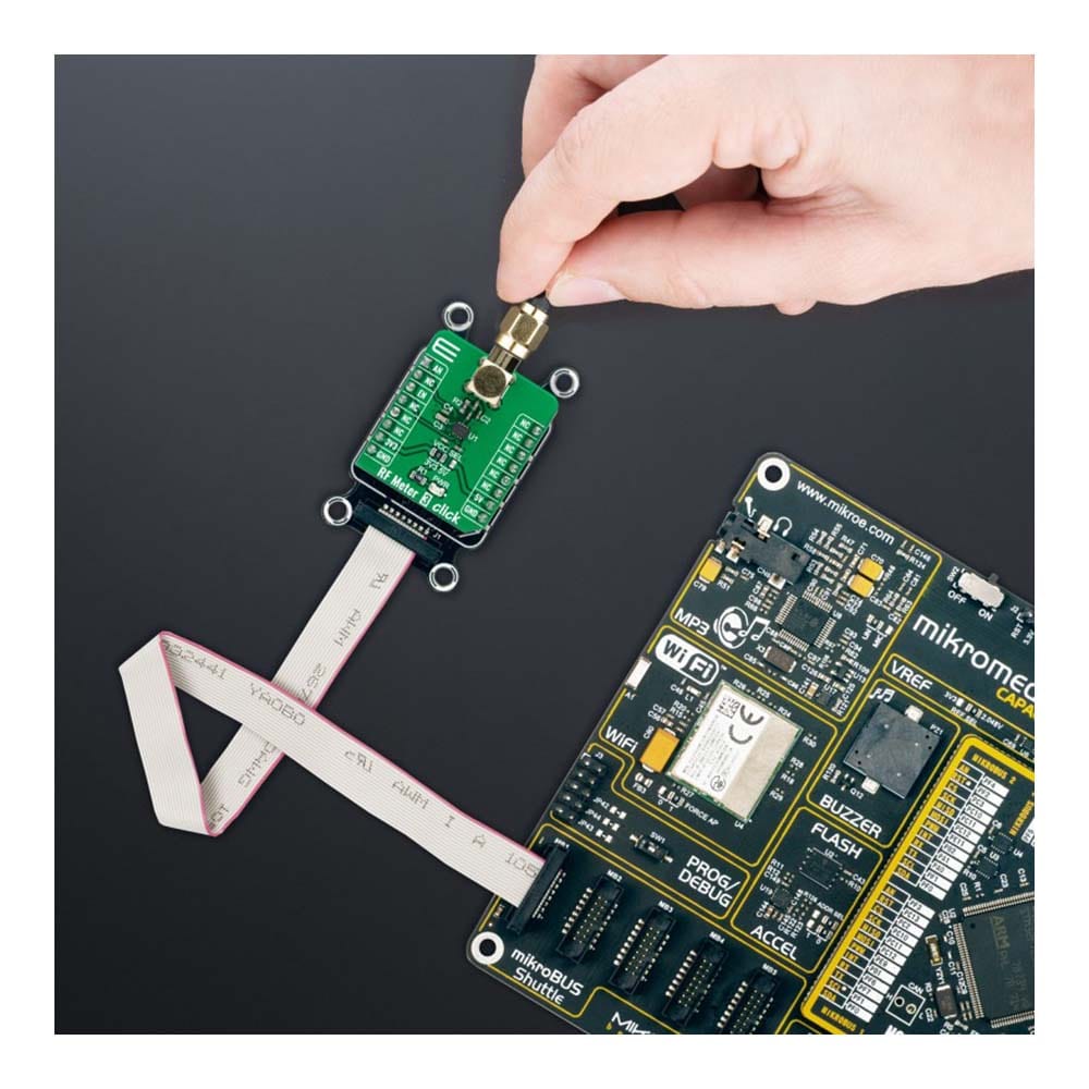
The RF Meter 3 Click Board™ is supported by a mikroSDK compliant library, which includes functions that simplify software development. This Click board™ comes as a fully tested product, ready to be used on a system equipped with the mikroBUS™ socket.
Downloads
Le RF Meter 3 Click Board™ est une carte complémentaire compacte qui collecte des informations, analyse la puissance RF et affiche les informations dans un format numérique facile à lire. Cette carte est équipée du LT5581, un détecteur de puissance RMS de précision monolithique à faible consommation d'Analog Devices. Le détecteur RMS utilise une technique exclusive pour mesurer avec précision la puissance RF dans une plage de 2 GHz à 2,6 GHz, bien adaptée aux signaux avec des facteurs de crête élevés. Il génère une tension continue à échelle linéaire proportionnelle à la puissance d'un signal d'entrée RF en dBm. Cette carte Click™ convient à la mesure et au contrôle de puissance de précision pour diverses normes RF, notamment GSM/EDGE, CDMA, CDMA2000, W-CDMA, TD-SCDMA, UMTS, LTE et WiMAX.
La carte Click™ RF Meter 3 est prise en charge par une bibliothèque compatible mikroSDK, qui comprend des fonctions qui simplifient le développement logiciel. Cette carte Click™ est livrée sous la forme d'un produit entièrement testé, prêt à être utilisé sur un système équipé de la prise mikroBUS™.
| General Information | |
|---|---|
Part Number (SKU) |
MIKROE-4906
|
Manufacturer |
|
| Physical and Mechanical | |
Weight |
0.02 kg
|
| Other | |
EAN |
8606027389351
|
Frequently Asked Questions
Have a Question?
Be the first to ask a question about this.