

Mikroelektronika d.o.o.
Carte à clic ADC 15
Carte à clic ADC 15
SKU: MIKROE-4890
Impossible de charger la disponibilité du service de retrait


Key Features
Overview
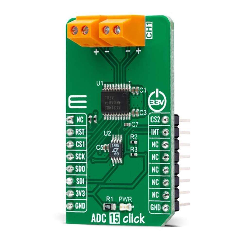
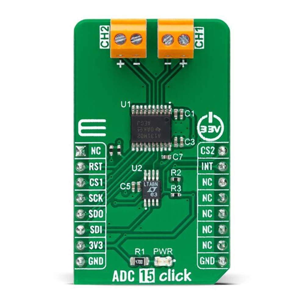
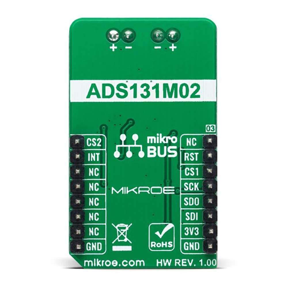
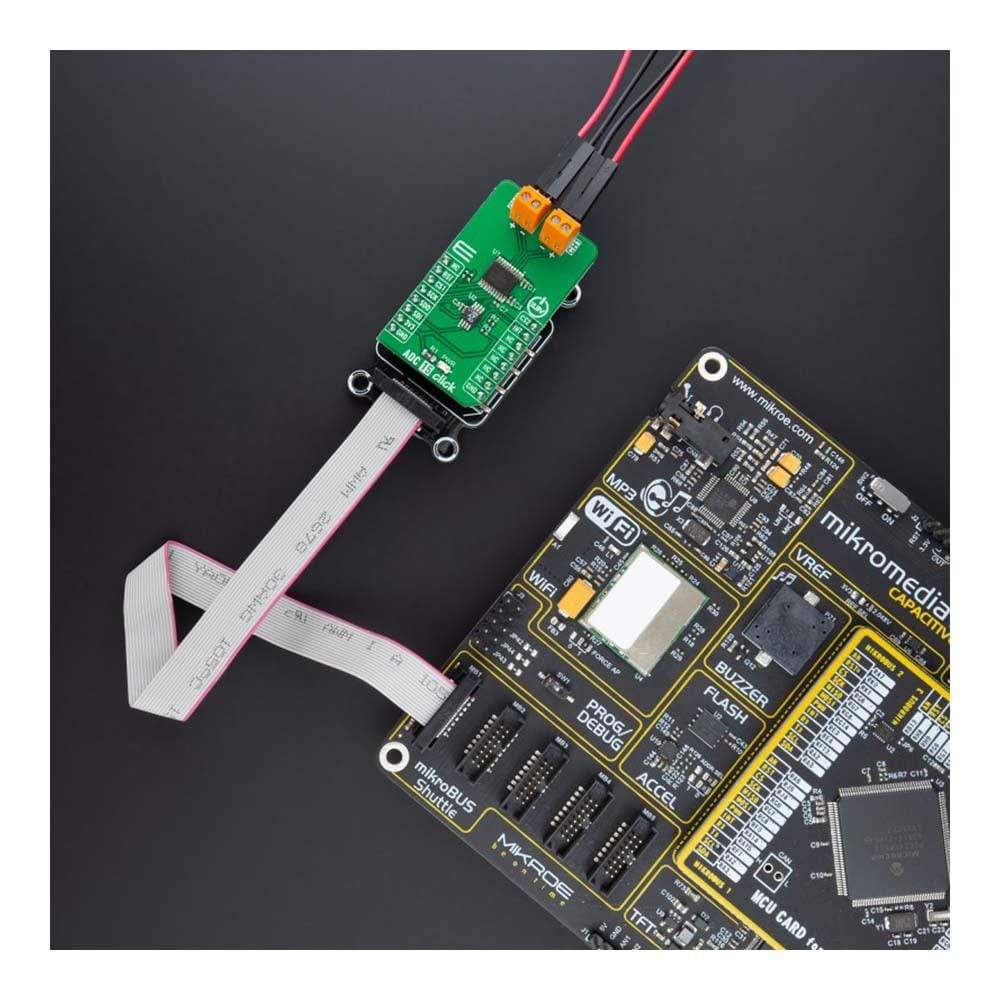
The ADC 15 Click Board™ is a compact add-on board that contains a high-performance data converter. This board features the ADS131M02, a two-channel, simultaneously sampling, 24-bit, delta-sigma (ΔΣ), analogue-to-digital converter from Texas Instruments. The ADC inputs can be independently configured via serial peripheral interface depending on the sensor input. A low noise, programmable gain amplifier (PGA) provides gains ranging from 1 to 128 to amplify low-level signals. Additionally, this ADC integrates channel-to-channel phase, offset and gain calibration registers to help remove signal-chain errors alongside a low-drift, 1.2V integrated reference.
The ADC 15 Click Board™ offers a wide dynamic range, low power, and energy-measurement-specific features, making the device an excellent fit for energy metering, power metrology, and circuit breaker applications.
Downloads
Le Carte à clic ADC 15™ est une carte complémentaire compacte qui contient un convertisseur de données hautes performances. Cette carte comprend l'ADS131M02, un convertisseur analogique-numérique delta-sigma (ΔΣ) 24 bits à deux canaux et à échantillonnage simultané de Texas Instruments. Les entrées ADC peuvent être configurées indépendamment via une interface périphérique série en fonction de l'entrée du capteur. Un amplificateur à gain programmable (PGA) à faible bruit fournit des gains allant de 1 à 128 pour amplifier les signaux de faible niveau. De plus, cet ADC intègre des registres d'étalonnage de phase, de décalage et de gain canal à canal pour aider à éliminer les erreurs de chaîne de signal ainsi qu'une référence intégrée à faible dérive de 1,2 V.
La carte à clic ADC 15™ offre une large plage dynamique, une faible consommation et des fonctionnalités spécifiques à la mesure de l'énergie, ce qui fait de l'appareil un excellent choix pour les applications de comptage d'énergie, de métrologie de puissance et de disjoncteur.
| General Information | |
|---|---|
Part Number (SKU) |
MIKROE-4890
|
Manufacturer |
|
| Physical and Mechanical | |
Weight |
0.02 kg
|
| Other | |
EAN |
8606027384356
|
Frequently Asked Questions
Have a Question?
Be the first to ask a question about this.