


Mikroelektronika d.o.o.
Carte de clic pour moteur à courant continu 20
Carte de clic pour moteur à courant continu 20
SKU: MIKROE-4884
Impossible de charger la disponibilité du service de retrait

Overview
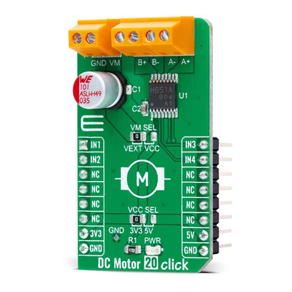
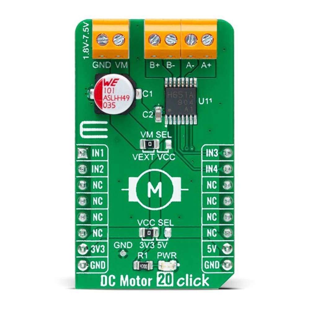
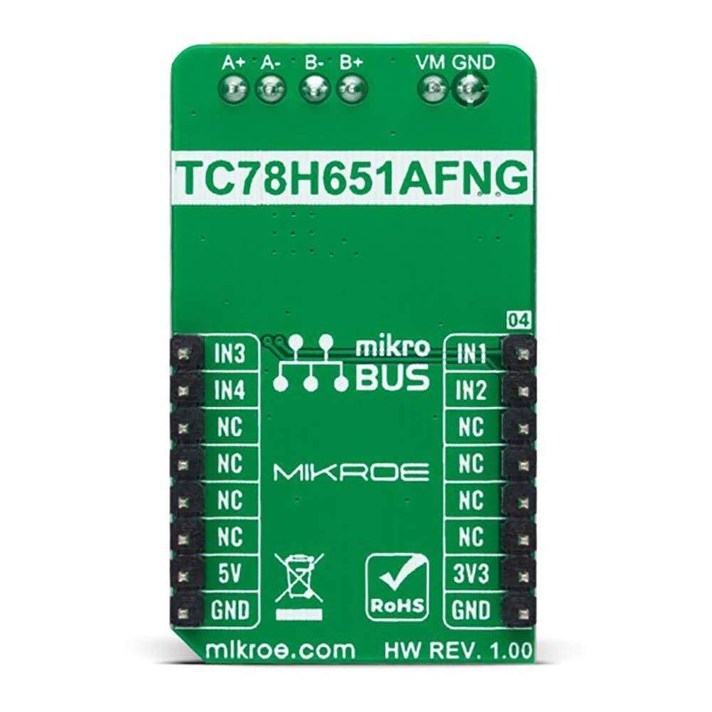
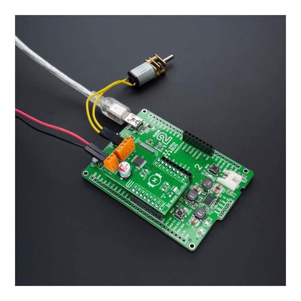
The DC Motor 20 Click Board™ is a compact add-on board that contains a brushed DC motor driver. This board features the TC78H651AFNG, a dual H-bridge driver for one or two DC brushed motors, which incorporates DMOS with low ON resistance in output transistors from Toshiba Semiconductor. The Forward/Reverse/Stop mode can be selected according to the state of its input control signals routed to the GPIO pins of the mikroBUS™ socket. It has a wide operating voltage range of 1.8V to 7.5V with an output current capacity of 2A maximum. Besides, it also features built-in protection against under-voltage, overcurrent, and overtemperature conditions.
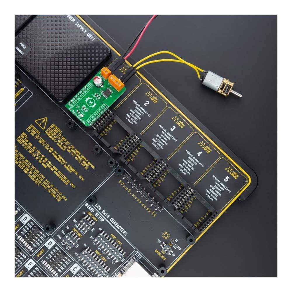
The DC Motor 20 Click Board™ is suitable for driving DC brushed motors and stepping motors for low voltage equipment.
Downloads
Le Moteur à courant continu 20 Click Board™ est une carte complémentaire compacte qui contient un pilote de moteur à courant continu à balais. Cette carte comprend le TC78H651AFNG, un pilote à double pont en H pour un ou deux moteurs à courant continu à balais, qui intègre un DMOS à faible résistance à l'état passant dans les transistors de sortie de Toshiba Semiconductor. Le mode Avant/Arrêt/Arrêt peut être sélectionné en fonction de l'état de ses signaux de commande d'entrée acheminés vers les broches GPIO du socket mikroBUS™. Il dispose d'une large plage de tension de fonctionnement de 1,8 V à 7,5 V avec une capacité de courant de sortie de 2 A maximum. En outre, il dispose également d'une protection intégrée contre les conditions de sous-tension, de surintensité et de surchauffe.
Le moteur à courant continu 20 Click Board™ convient à l'entraînement de moteurs à balais à courant continu et de moteurs pas à pas pour les équipements basse tension.
| General Information | |
|---|---|
Part Number (SKU) |
MIKROE-4884
|
Manufacturer |
|
| Physical and Mechanical | |
Weight |
0.02 kg
|
| Other | |
EAN |
8606027384059
|
Frequently Asked Questions
Have a Question?
Be the first to ask a question about this.