


Mikroelektronika d.o.o.
Planche à clic Buck 16
Planche à clic Buck 16
SKU: MIKROE-4846
Impossible de charger la disponibilité du service de retrait

Overview
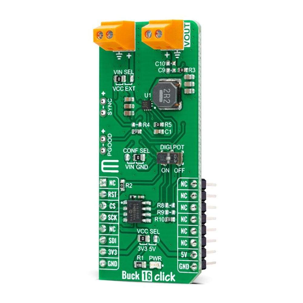
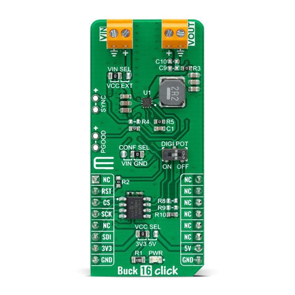
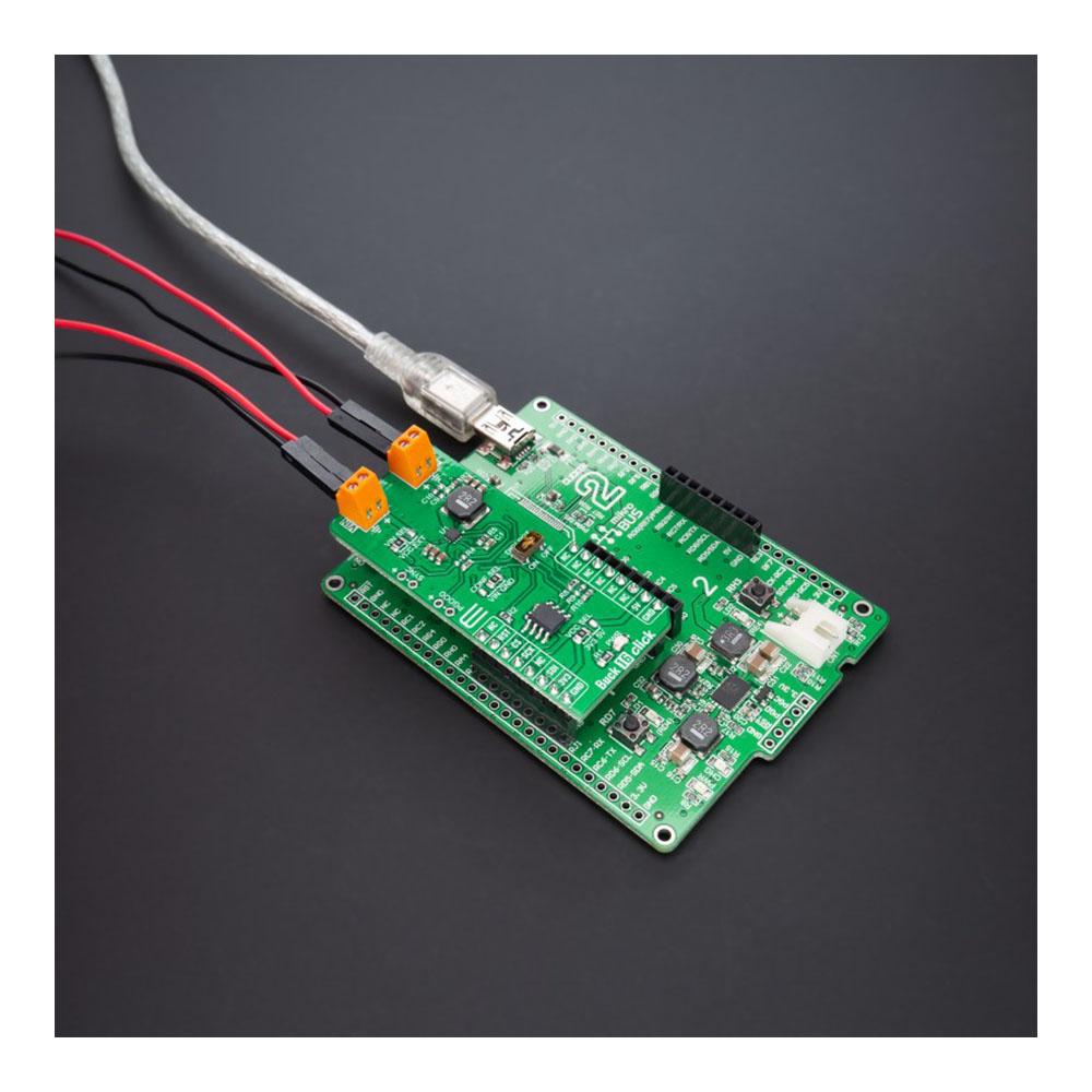
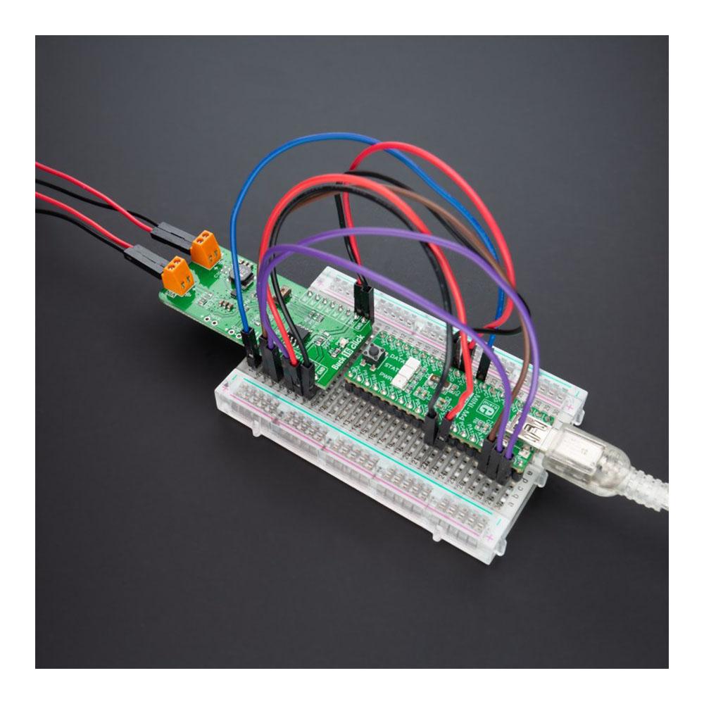
The Buck 16 Click Board™ is a compact add-on board that contains a DC-DC power converter that steps down the voltage from its input to its output. This board features the TPS62912, a high-efficiency, low noise, and low ripple current-mode synchronous buck converter from Texas Instruments. The TPS62912 has an output-voltage error of less than 1%, which helps ensure tight output-voltage accuracy, operates at a fixed switching frequency of 2.2MHz or 1MHz, and allows synchronization to an external clock.
The Buck 16 Click Board™ is suitable for noise-sensitive applications that generally use an LDO for post-regulation, such as high-speed ADCs, clock and jitter cleaner, serializer, de-serializer, and radar applications.
Downloads
Le Planche à clic Buck 16™ est une carte complémentaire compacte qui contient un convertisseur de puissance CC-CC qui abaisse la tension de son entrée à sa sortie. Cette carte est équipée du TPS62912, un convertisseur abaisseur synchrone en mode courant à haut rendement, à faible bruit et à faible ondulation de Texas Instruments. Le TPS62912 a une erreur de tension de sortie inférieure à 1 %, ce qui contribue à garantir une précision de tension de sortie stricte, fonctionne à une fréquence de commutation fixe de 2,2 MHz ou 1 MHz et permet la synchronisation avec une horloge externe.
Le Buck 16 Click Board™ convient aux applications sensibles au bruit qui utilisent généralement un LDO pour la post-régulation, telles que les CAN à grande vitesse, les nettoyeurs d'horloge et de gigue, les sérialiseurs, les désérialiseurs et les applications radar.
| General Information | |
|---|---|
Part Number (SKU) |
MIKROE-4846
|
Manufacturer |
|
| Physical and Mechanical | |
Weight |
0.02 kg
|
| Other | |
EAN |
8606027383984
|
Frequently Asked Questions
Have a Question?
Be the first to ask a question about this.