


Mikroelektronika d.o.o.
Tableau de clic Fan 8
Tableau de clic Fan 8
SKU: MIKROE-4824
Impossible de charger la disponibilité du service de retrait


Overview
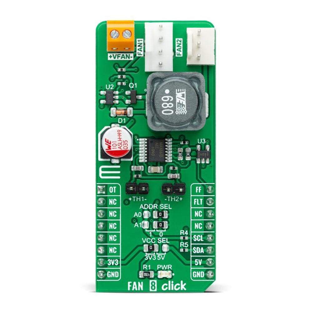
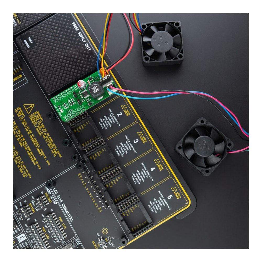
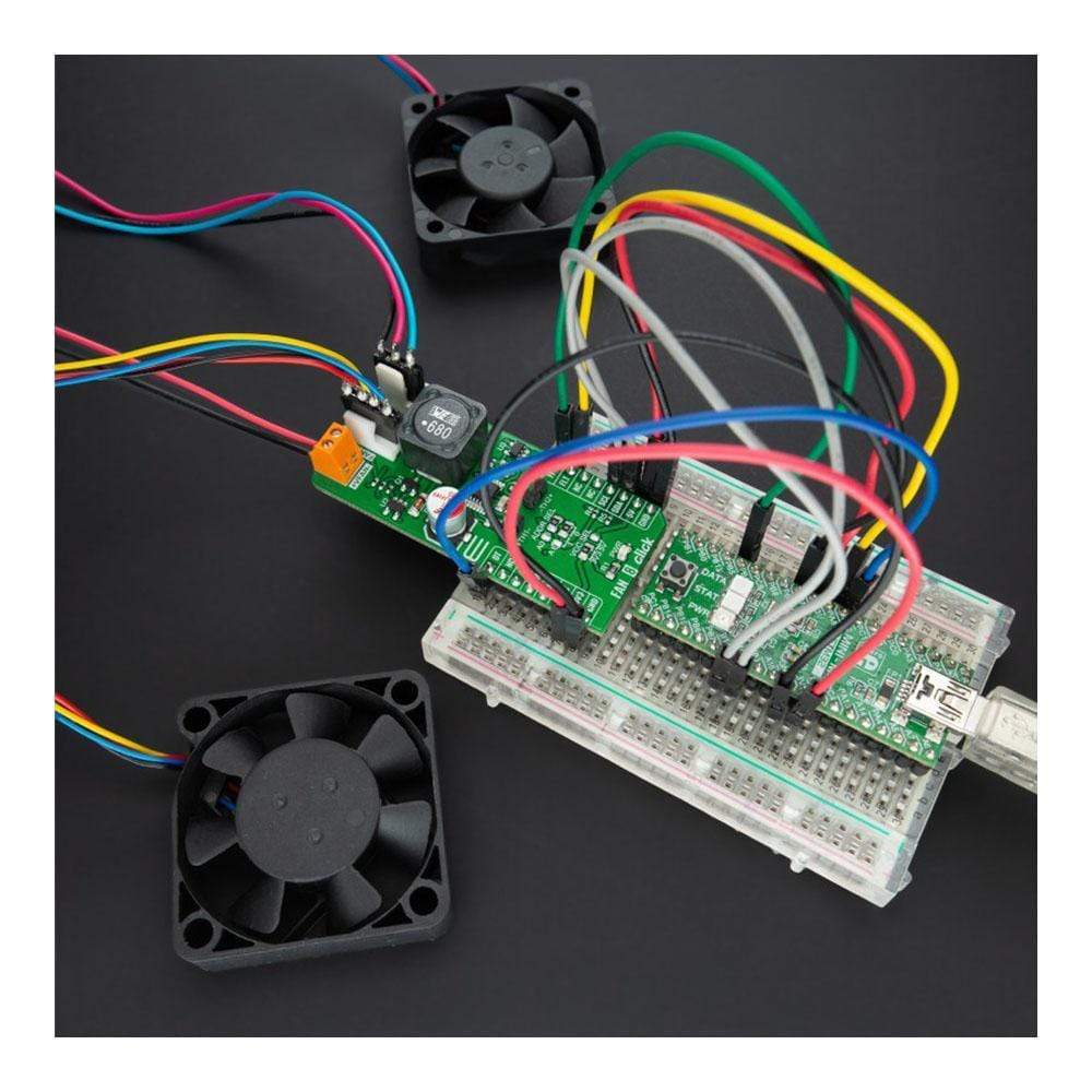
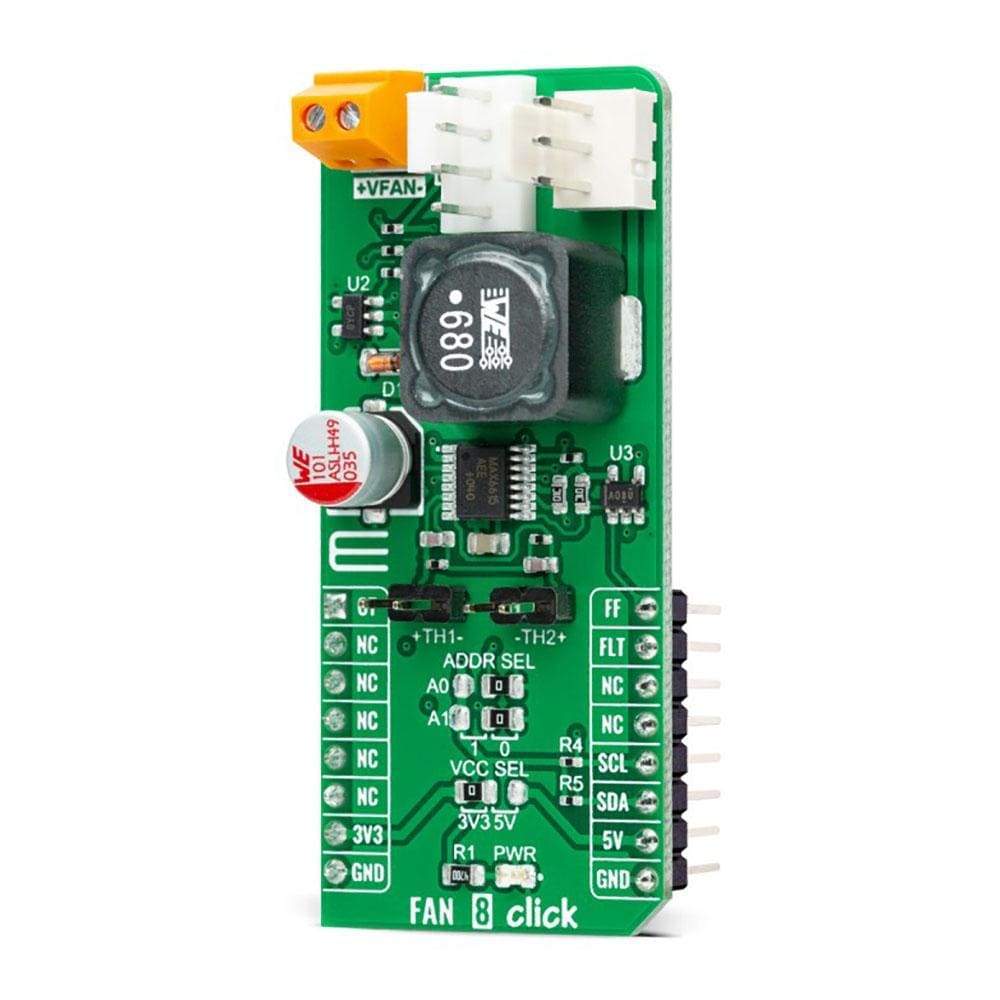
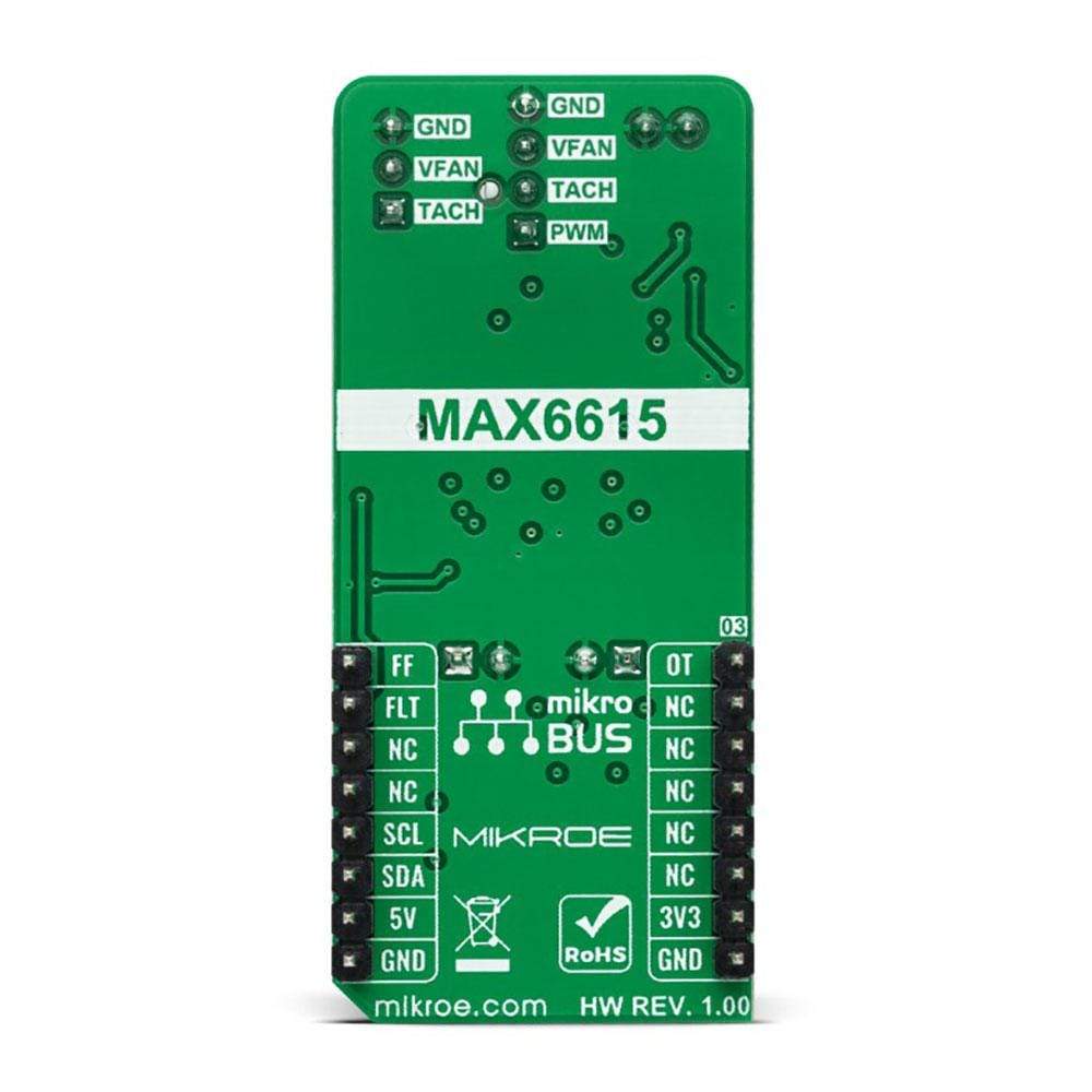
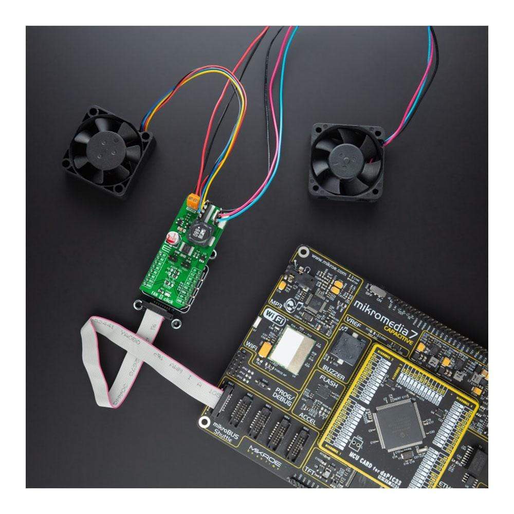
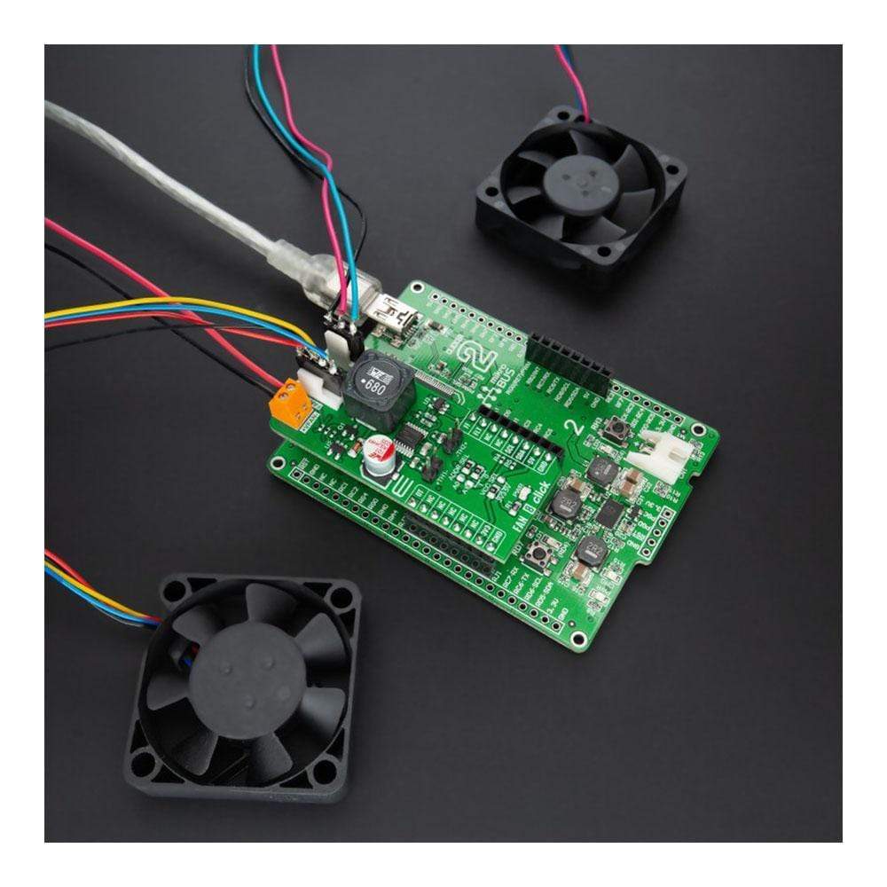
The Fan 8 Click Board™ is a compact add-on board that represents a compliant fan controller. This board features the MAX6615, a fan-speed controller, and a dual-channel temperature monitor with external thermistor inputs from Maxim Integrated, now part of Analog Devices. The MAX6615 controls the speed of two cooling fans based on the temperatures of external thermistors and the device's internal temperature, reporting temperature values in a digital form using the I2C serial interface. The temperature data controls a PWM output signal to adjust the speed of a cooling fan, minimizing noise when the system is running cool, but providing maximum cooling when power dissipation increases.
It also features an overtemperature alarm to generate interrupts, throttle, or shutdown signals. The combination of high accuracy and dual thermistor inputs makes this Click board a practical choice for networking equipment, servers, or other applications requiring cooling and temperature control.
Downloads
Le Fan 8 Click Board™ est une carte complémentaire compacte qui représente un contrôleur de ventilateur conforme. Cette carte comprend le MAX6615, un contrôleur de vitesse de ventilateur et un moniteur de température à deux canaux avec entrées de thermistance externes de Maxim Integrated, qui fait désormais partie d'Analog Devices. Le MAX6615 contrôle la vitesse de deux ventilateurs de refroidissement en fonction des températures des thermistances externes et de la température interne de l'appareil, en signalant les valeurs de température sous forme numérique à l'aide de l'interface série I2C. Les données de température contrôlent un signal de sortie PWM pour ajuster la vitesse d'un ventilateur de refroidissement, minimisant le bruit lorsque le système fonctionne à froid, mais fournissant un refroidissement maximal lorsque la dissipation de puissance augmente.
Il est également doté d'une alarme de surchauffe pour générer des signaux d'interruption, d'accélération ou d'arrêt. La combinaison d'une haute précision et de deux entrées de thermistance fait de cette carte Click un choix pratique pour les équipements réseau, les serveurs ou d'autres applications nécessitant un refroidissement et un contrôle de la température.
| General Information | |
|---|---|
Part Number (SKU) |
MIKROE-4824
|
Manufacturer |
|
| Physical and Mechanical | |
Weight |
0.02 kg
|
| Other | |
EAN |
8606027383915
|
Frequently Asked Questions
Have a Question?
Be the first to ask a question about this.