Carte à clic pour décodeur DTMF
Overview
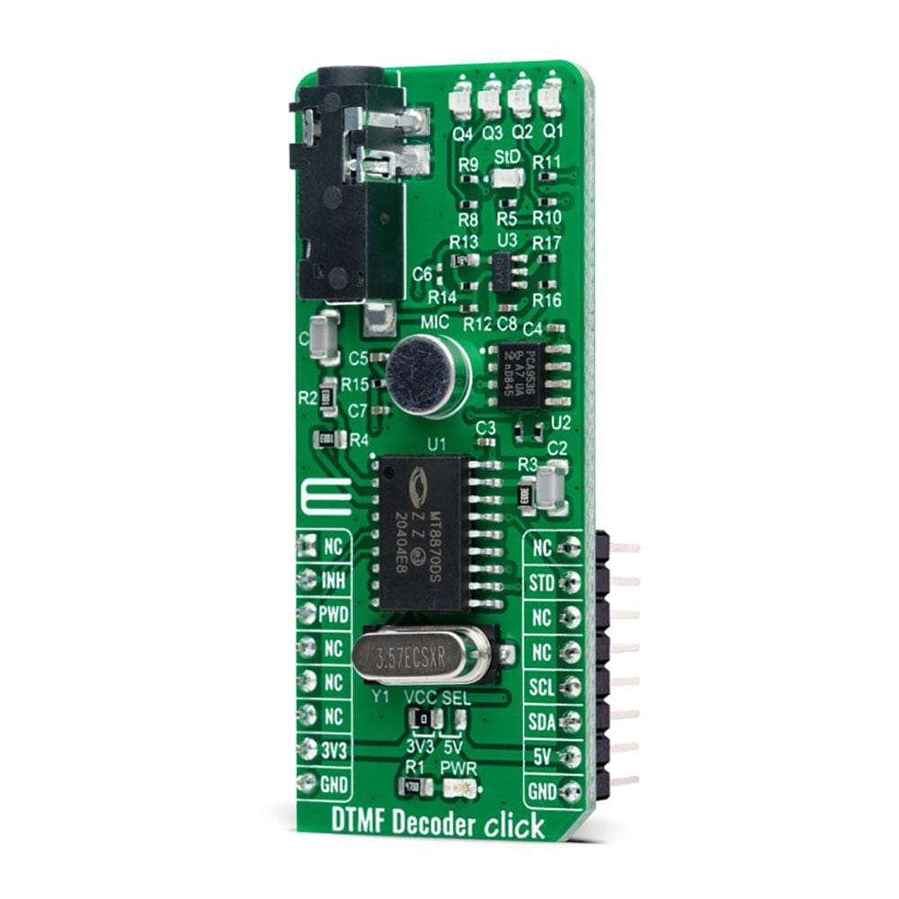
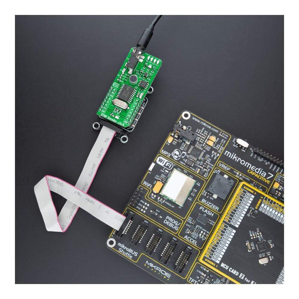
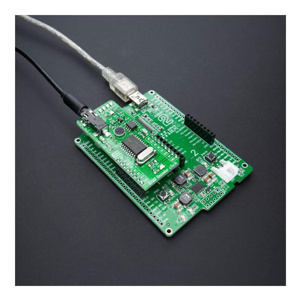
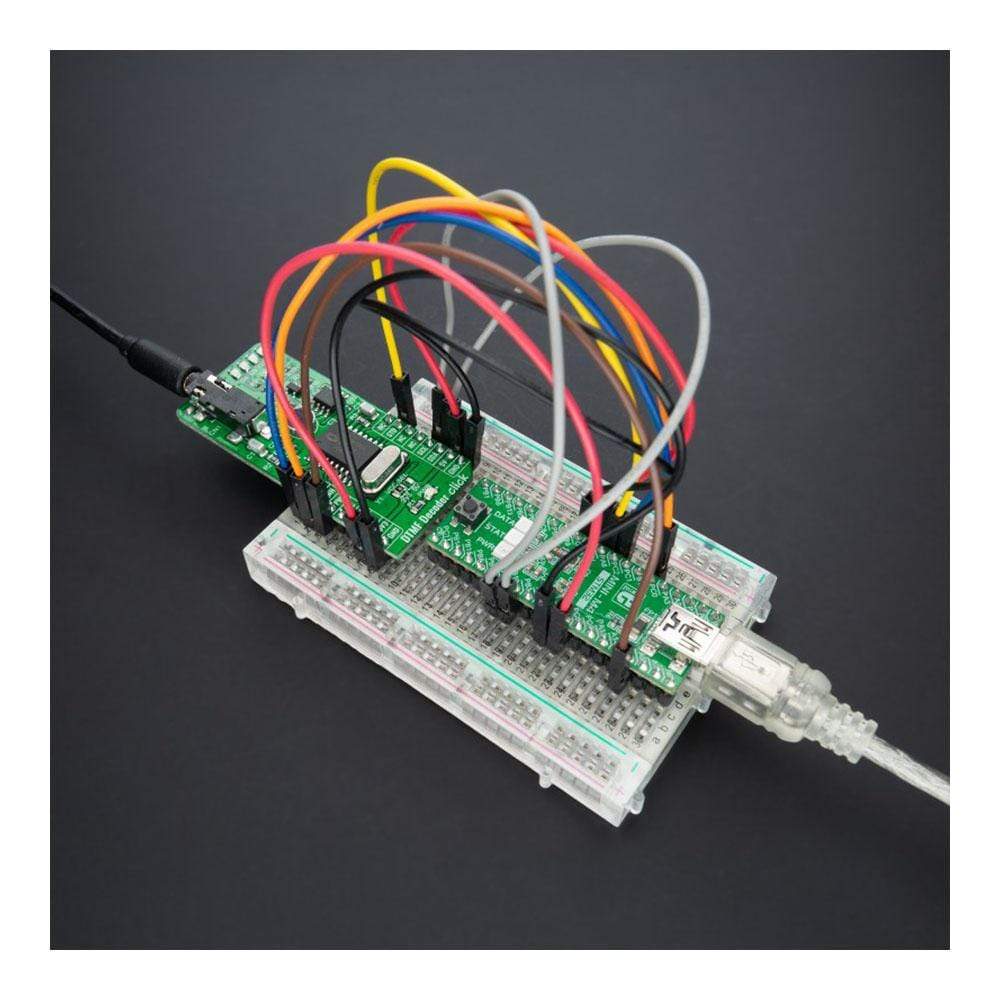
Le Le décodeur DTMF Click Board™ est une carte complémentaire compacte qui contient un récepteur DTMF intégré avec une sensibilité améliorée. Cette carte comprend le MT8870D, un récepteur DTMF complet intégrant le filtre à division de bande et les fonctions de décodeur numérique de Microchip Technology. Il offre une faible consommation d'énergie et des performances élevées et utilise des techniques de comptage numérique pour détecter et décoder les 16 paires de tonalités DTMF en un code à 4 bits. Chaque fois qu'une tonalité valide est détectée, il génère la valeur associée en binaire sur quatre LED, avec un indicateur supplémentaire qui clignote après chaque nouvelle tonalité. Ce Click Board™ convient aux systèmes de radiomessagerie, à la télécommande, aux circuits de communication électronique et à diverses autres applications.
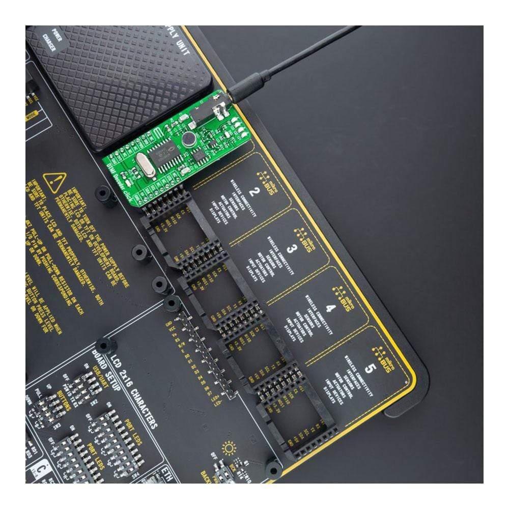
Le décodeur DTMF Click Board™ est pris en charge par une bibliothèque compatible mikroSDK, qui comprend des fonctions qui simplifient le développement logiciel. Ce Click Board™ est un produit entièrement testé, prêt à être utilisé sur un système équipé de la prise mikroBUS™.
How Does The DTMF Decoder Click Board™ Work?
The DTMF Decoder Click Board™ is based on the MT8870D, an integrated DTMF receiver with enhanced sensitivity from Microchip Technology. It offers low power consumption and high performance and consists of a band split filter section, which separates the high and low group tones, followed by a digital counting section that verifies the received tones' frequency and duration before passing the corresponding code to the output bus.
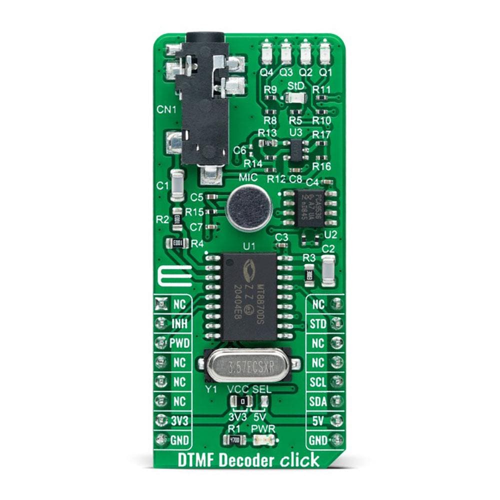
The DTMF Decoder Click Board™ has two ways to detect tones: with a mobile phone with a 3.5mm jack which provides the DTMF signals to MT8870D decoder, or using an onboard microphone used to listen the DTMF tones generated by the cell phone. The MT8870D uses digital counting techniques to detect and decode all 16 DTMF tone-pairs into a 4-bit code.
The DTMF Decoder Click Board™ communicates with MCU using standard I2C 2-Wire interface, with a clock frequency up to 100kHz in the Standard and 400kHz in the Fast Mode. Using the PCA9536 port expander that communicates with the MCU via I2C communication, it is possible to visually display, in binary form, the digit of the pressed number. The digit in binary form is then visually displayed using four red LEDs, labelled from Q1 to Q4, located in the board's upper right corner.
The DTMF Decoder Click Board™ also has a power-down feature routed on the CS pin of the mikroBUS™ socket labelled as PWD. A logic high applied to pin PWD will power down the device to minimize the power consumption in a Standby mode, which stops the oscillator and the filters' functions. Also, it uses the interrupt pin of the mikroBUS™ labelled as STD with an additional LED indicator signaling that a received tone pair has been registered, and INH pin, which inhibits the detection of tones representing characters A, B, C, and D. The output code will remain the same as the previously detected code.
The DTMF Decoder Click Board™can operate with both 3.3V and 5V logic voltage levels selected via the VCC SEL jumper. This way, it is allowed for both 3.3V and 5V capable MCUs to properly use the I2C communication lines. However, the Click board™ comes equipped with a library containing easy-to-use functions and an example code that can be used, as a reference, for further development.
SPECIFICATIONS
Type | Signal Processing |
Applications | Can be used for paging systems, remote control, electronic communications circuits, and various other applications. |
On-board modules | MT8870D - an integrated DTMF receiver with enhanced sensitivity from Microchip Technology |
Key Features | Low power consumption, complete DTMF receiver, high performance, internal gain setting amplifier, power-down mode, inhibit mode, and more. |
Interface | I2C |
Compatibility | mikroBUS |
Click board size | L (57.15 x 25.4 mm) |
Input Voltage | 3.3V or 5V |
PINOUT DIAGRAM
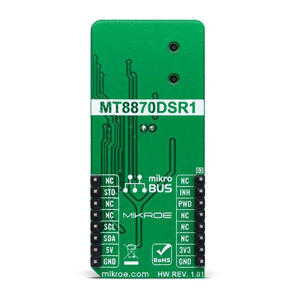
This table shows how the pinout of the DTMF Decoder Click Board™ corresponds to the pinout on the mikroBUS™ socket (the latter shown in the two middle columns).
Notes | Pin | Pin | Notes | ||||
---|---|---|---|---|---|---|---|
NC | 1 | AN | PWM | 16 | NC | ||
Inhibit Mode | INH | 2 | RST | INT | 15 | STD | New Tone Indicator |
Power Down Mode | PWD | 3 | CS | RX | 14 | NC | |
NC | 4 | SCK | TX | 13 | NC | ||
NC | 5 | MISO | SCL | 12 | SCL | I2C Clock | |
NC | 6 | MOSI | SDA | 11 | SDA | I2C Data | |
Power Supply | 3.3V | 7 | 3.3V | 5V | 10 | 5V | Power Supply |
Ground | GND | 8 | GND | GND | 9 | GND | Ground |
ONBOARD SETTINGS AND INDICATORS
Label | Name | Default | Description |
---|---|---|---|
LD1 | PWR | - | Power LED Indicator |
LD2 | StD | - | New Tone LED Indicator |
LD3-LD6 | Q1 - Q4 | - | Pressed-Number LED Indicator |
JP1 | VCC SEL | Left | Logic Level Voltage Selection 3V3/5V: Left position 3V3, Right position 5V |
DTMF DECODER CLICK ELECTRICAL SPECIFICATIONS
Description | Min | Typ | Max | Unit |
---|---|---|---|---|
Supply Voltage | 3.3 | - | 5 | V |
Frequency | - | 3.579545 | - | MHz |
Power Consumption | - | 15 | - | mW |
Operating Temperature Range | -40 | +25 | +85 | °C |
Software Support
We provide a library for the DTMF Decoder Click Board™ as well as a demo application (example), developed using MikroElektronika compilers. The demo can run on all the main MikroElektronika development boards.
The package can be downloaded/installed directly from NECTO Studio The package Manager (recommended), downloaded from our LibStock™ or found on mikroE Github account.
Library Description
This library contains API for the DTMF Decoder Click Board™ driver.
Key Functions
dtmfdecoder_cfg_setup
- Config Object Initialization function.dtmfdecoder_init
- Initialization function.dtmfdecoder_default_cfg
- Click Default Configuration function.
Example Description
This example shows the basic tone capture of DTMF frequencies, decoding and representing them on the UART LOG.
void application_task ( void ) { uint8_t result; if ( dtmfdecoder_delayed_steering_check( &dtmfdecoder ) ) { result = dtmfdecoder_tone_read( &dtmfdecoder ); log_printf( &logger, " Detected key tone:t%crn", result ); Delay_ms( tone_register_delay ); } }
The full application code, and ready-to-use projects can be installed directly from NECTO Studio The package Manager (recommended), downloaded from our LibStock™ or found on the mikroE Github account.
Other mikroE Libraries used in the example:
- MikroSDK.Board
- MikroSDK.Log
- Click.DTMFDecoder
Additional Notes and Information
Depending on the development board you are using, you may need USB UART Click Board™, USB UART 2 Click Board™ or RS232 Click Board™ to connect to your PC, for development systems with no UART to USB interface available on the board. The terminal available in all MikroElektronika compilers, or any other terminal application of your choice, can be used to read the message.
MIKROSDK
The DTMF Decoder Click Board™ is supported with mikroSDK - MikroElektronika Software Development Kit. To ensure proper operation of mikroSDK compliant Click board™ demo applications, mikroSDK should be downloaded from the LibStock and installed for the compiler you are using.
Frequently Asked Questions
Have a Question?
Be the first to ask a question about this.